
Following the development of the Zergling robot LINK, i decided to build his bigger brother the Roach, as shown in figure 1. Again, for those of you who don't recognise the name a creature from the Starcraft universe LINK. Previously the aim was to develop a robot that demonstrated how the analogue circuits taught in the FESC module could be used in the real world, in this case to develop a four neuron neural network (confess slightly stretching the definition of a neural network). However, you can only do so much with four neurons, did look into expanding this robot's processing power, but implementing more complex functions from operational amplifiers was proving a little tricky e.g. to get the robot to stop to recharge or eat food required a neuron based on a multiplier, multiplication by a constant is easy, multiplication by a variable not nice. Could of made a hybrid solution using operational amplifiers and digital logic, but this felt like cheating, therefore i turned to the BBC Micro:Bit.
Version 1.0 : BBC Micro:Bit
Pin through board version 1.0
Pin through board version 1.1

Figure 1 : Roach
Why the BBC Micro:Bit? Well this all came about after a talk with David and a discussion of how there was a hole in the market for a cheap (very cheap), easy to build robot for schools. These micro-controller boards were given to every year 7 (11 and 12 year old) child in Britain starting from October 2015 (LINK). This micro-controller is based around the ARM Nordic nRF51822 with 16K RAM, 256K Flash. At its heart is an ARM Cortex-M0 processor coupled to an accelerometer, magnetometer, Bluetooth, USB, 25 LEDs and two programmable buttons. Adding this controller to the Zergling is easy as its edge connector externalises its SPI, I2C and UART interfaces. Designing a solution that can be built by school children in schools, thats a slightly more tricky problem. Currently the plan is to build two versions:

Figure 2 : BBC micro:bit
With the previous op-amp based robot, going to a split rail supply made sense as we needed a positive and a negative voltage for the op-amps, this also greatly simplifies the circuits needed to reverse the motor direction. For the micro:bit not so sure, these work off 3.3V so would need a big step down from a 9V battery, also would have unequal power usage between the two 9V batteries i.e. negative cells would have a lighter load. Therefore, if we move to a single rail supply e.g. 4.5V, 3 x AA cells, we will need H-bridges to reverse the voltage across the motors. To reduce costs will go for a discrete transistor solution, as shown in figure 3. Slightly messy solution, would of been far easier to go to a standard H-bridge IC, but this would of increased costs and soldering complexity i.e. surface mount. Currently Roach version 1.0 has:
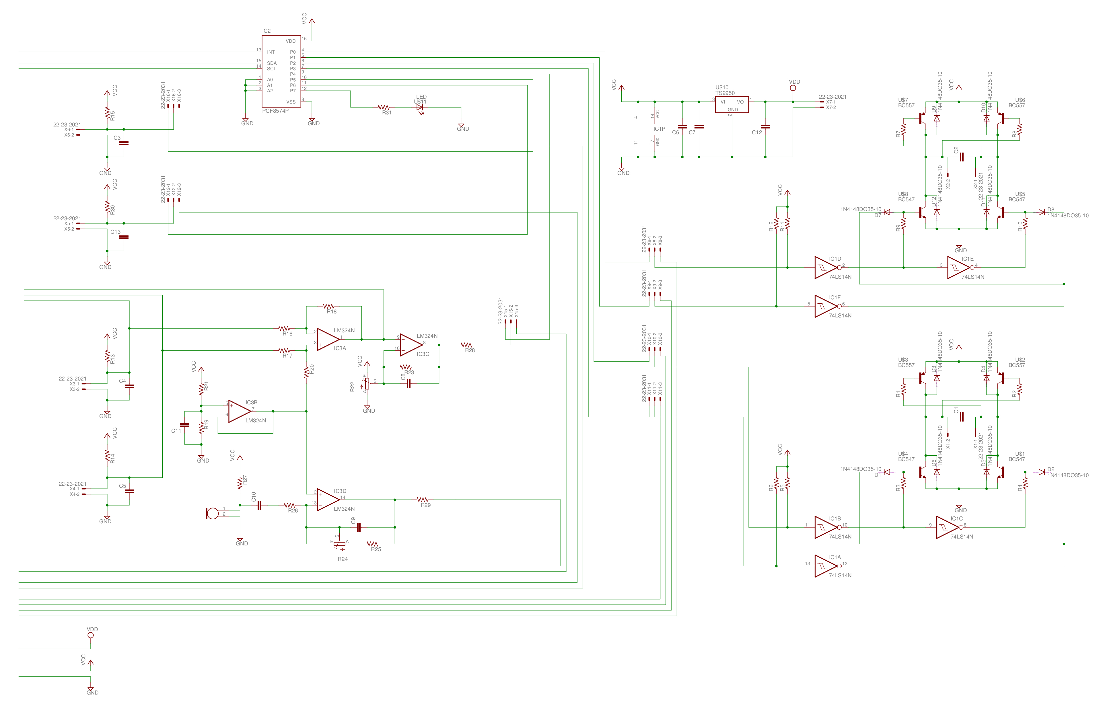
Figure 3 : Schematic V1.0
The move from 9V to 4.5V means a change in the chassis, also the edge connector (LINK) used by the mico-bit is a lot wider than the existing robot, as shown in figure 4. Now looking at 70 - 80mm wide, a round and fat robot, rather than the longer thinner Zergling, which fortunately fits in with the game graphics. The new 3D model is shown in figure 5. The robot has a shell, which covers the front half, but still allows you to see the LED matrix and access the the two push buttons on the micro:bit. The front 'beak', or hook will be curved using a soldering iron or hot air gun after printing. Will also print out and glue on a few spikes/spines. The front claws will again be used to mount the two front bump switches.
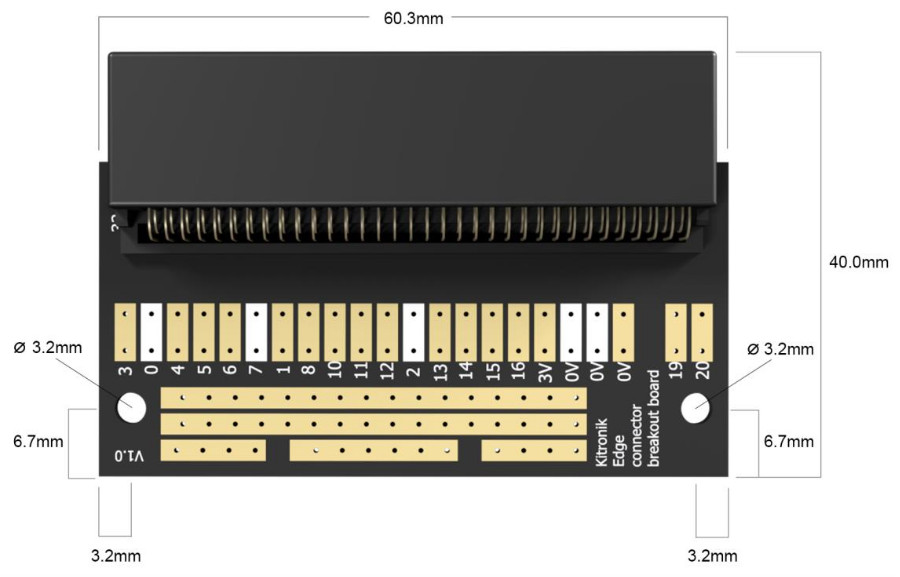
Figure 4 : Micro:bit edge connector
At the heart of this chassis is the battery pack. I have tried to design my own in the past, but found them quite tricky, therefore will use this very nice design from Thingiverse (LINK), as shown in figure 6. Again, will use the same motor/gearbox to drive the legged wheels. The 3D models of the robots chasis can be downloaded here: (LINK).
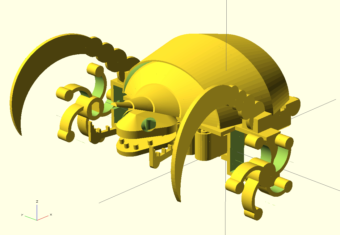
Figure 5 : Version 1.0 - 3D printing
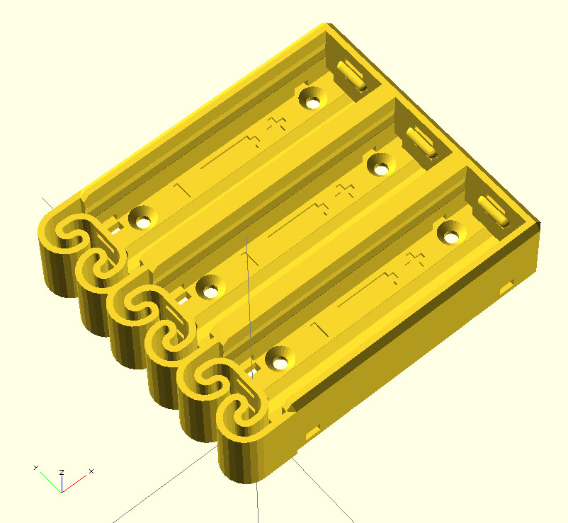
Figure 6 : Battery pack 3D model
Testing, starting with the motor controllers. Was slightly concerned with the current ratings of the standard BC547/BC557 e.g. stall currents can be quite large, but we are using three series AA batteries, so this will be limited, but decided to play safe and switched to 2N4401 (LINK) and the 2N4403 (LINK). These are the same size but have a max Ic of 500mA. Initial testing was down on bread board, as shown in figure 7, partial success, the stop control lead turned out to be more of a slow control lead. To be honest thought it was a bit of gamble i.e. 0.7V of the Silicon transistor compared to the 0.6V of the Germanium diode, the transistor would always start to turn on. Solution use a Darlington pair (LINK), this increases the current gain, which is always good, but more importantly increases the turn-on base-emitter voltage to 1.4V. To implement this pair used a BC547 and a 2N4401, could of just used two 2N4401, but had already bought the BC547s, final circuit is shown in figure 8 (opps some of the resistor values are wrong, 1K = 4K7).
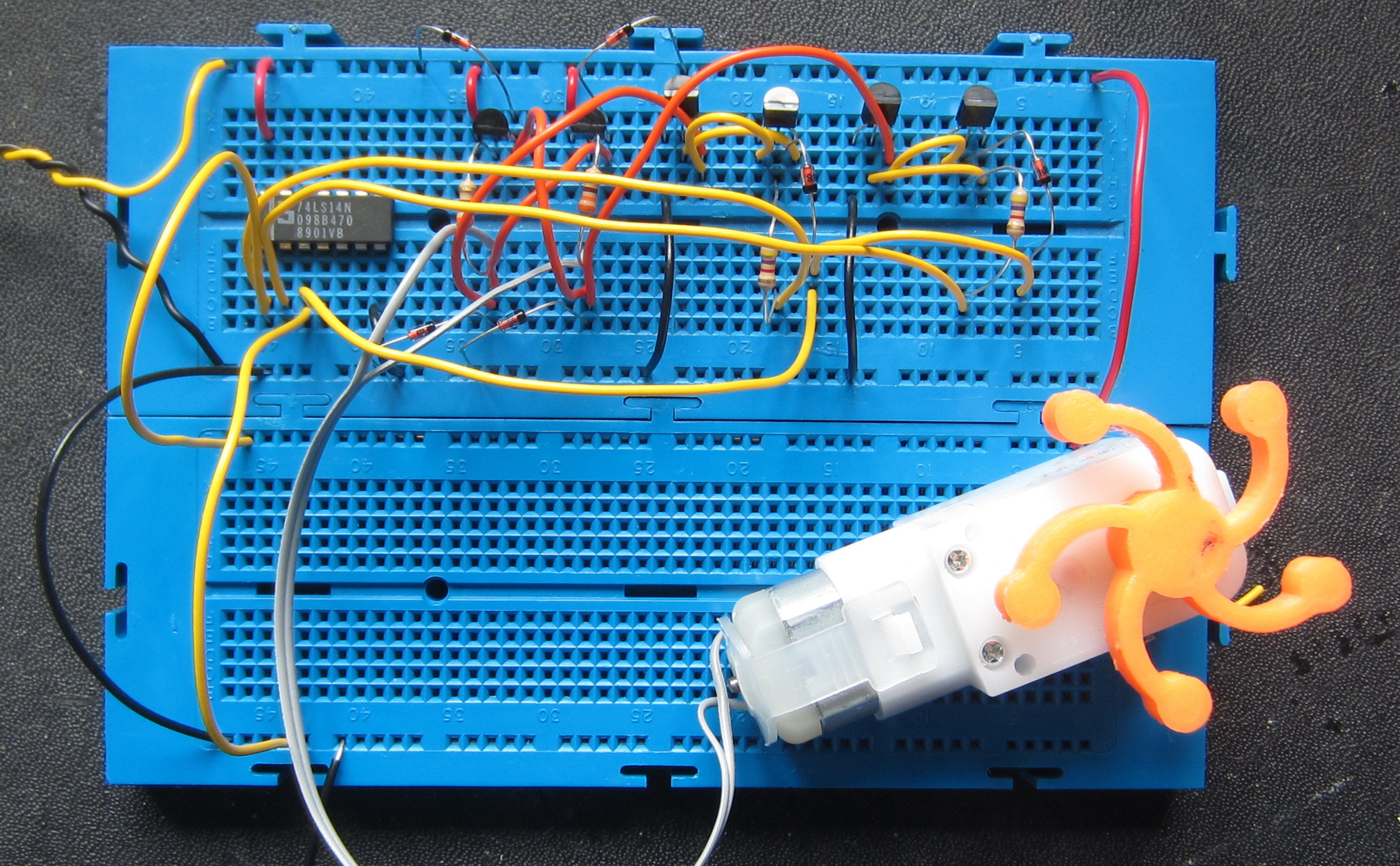
Figure 7 : H-bridge test circuit
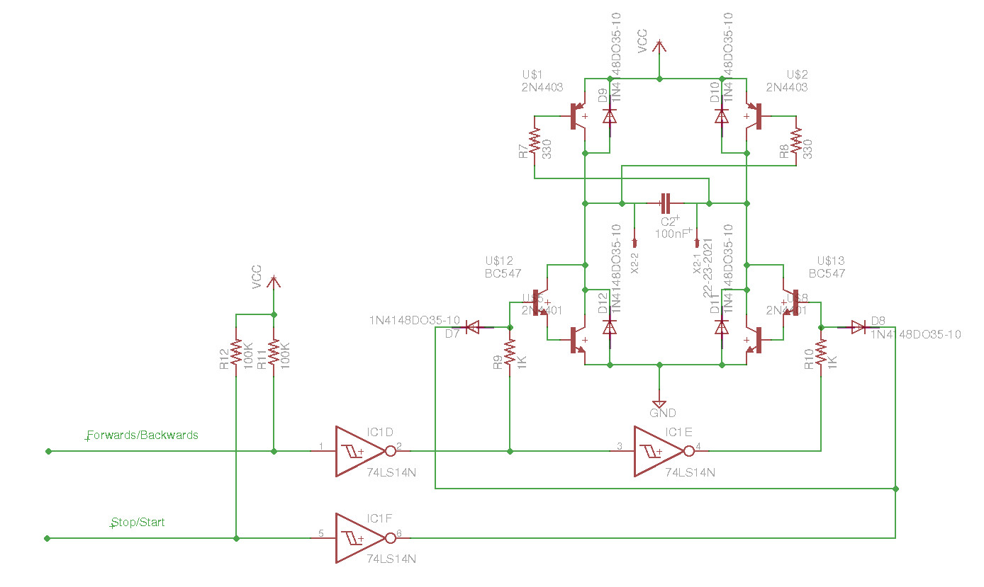
Figure 8 : H-bridge - schematic V1.1
Been reading the BBC micro:bit MicroPython documentation (LINK) , one thing that looks interesting is the sound element. They recommend that you use a loud speaker and not using a piezo electric buzzer. I guess they should of defined the difference between a transducer and a buzzer. Piezo electric transducers such as these (LINK) are fine. I can kind of see their point i.e. piezo electric devices are not as good as loudspeakers, have a limited range, towards the top end, but their key advantage is that you do not need a driver stage. During testing i found the true use of the Micro:bit in this code (after 2 hours its funny, trust me):
from microbit import *
import music

while True:
    display.show(Image.HAPPY)
    music.play(music.NYAN)
    display.show(Image.CONFUSED)
    music.play(music.NYAN)
    display.show(Image.ANGRY)
    music.play(music.NYAN)
Modified the schematic, adding an extra header to allow a Piezo electric transducer to be connected to pin0. May be wrong but there doesn't seem to be a way of re-mapping this pin to another output. The next element to test is the analogue section i.e. the operational amplifiers (LDR pre-processing and audio microphone) and raw LDR signals. The micro:bit has six 10bit ADC, 0V - 3.3V, (0V=0, 3.3V=1023). The operational amplifiers are powered (at present) by +4.5V, normal op-amps always saturate a volt or two from the supply rail so their max output voltage will be in the right ball park. Test system is shown in figure 9. Microphone circuit and outputs shown in figures 11 - 13.
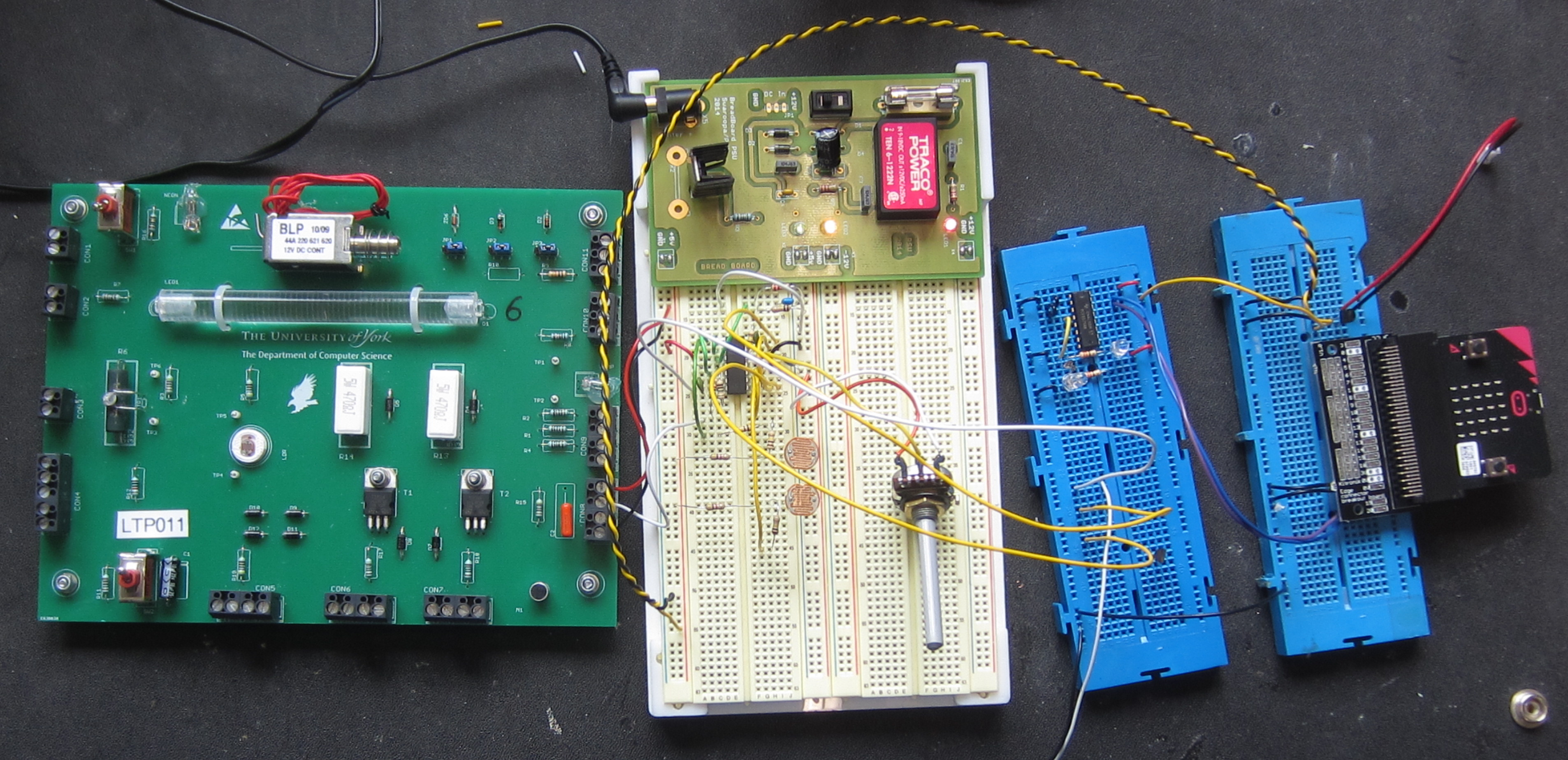
Figure 9 : test system
Figure 10 : microphone
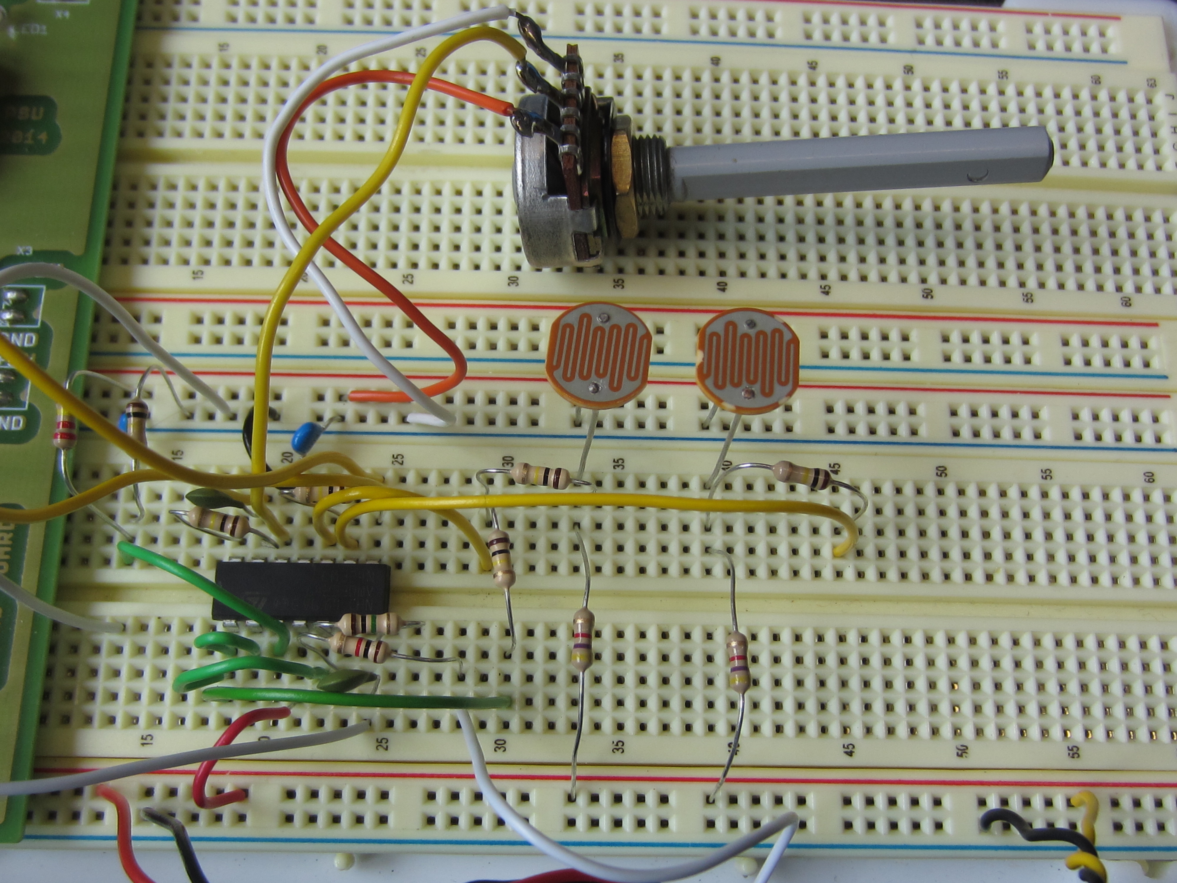
Figure 11 : operational amplifier test circuit
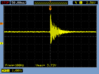
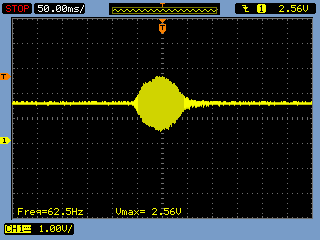
Figure 12 : oscillascope traces, clap (left), whistle (right)
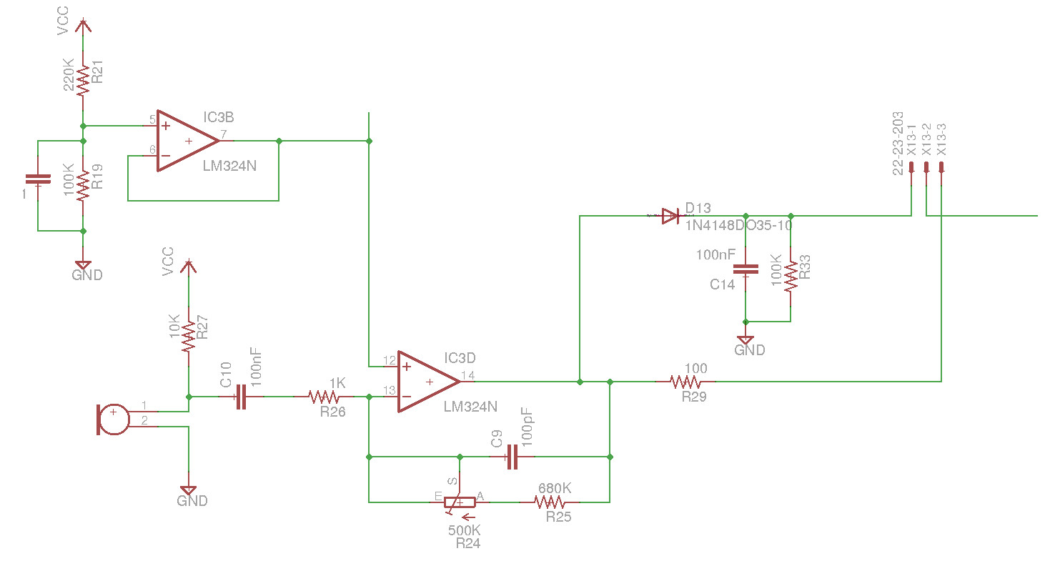
Figure 13 : Microphone test circuit
I was a bit worried about a single stage amplifier with quite a large gain i.e. oscillation, so added a small bypass cap across the feedback resistor, however, seemed quite stable. Figure 12 shows the operational amplifiers output at approximately 50cm. In operation the software running the robot will be doing lots of stuff so you can't allocate the full processor load i.e. you may not be able to sample the signal fast enough, also perhaps not needed anyway. Therefore, added a peak detector (diode + RC) to hold the max output. This works quite well as a clap trigger i.e. clap twice to start the robot, holding the peak voltage until the polling loop got round to reading it, code shown in figure 16 (very simple, need to add timeouts). LDR sensors also worked fine, no obvious problems driving the ADC inputs using circuits with a high output impedance.
Initially i developed the MicroPython software using the web based develop tools, however, these are a little bit clunky i.e. have to keep downloading hex files. However, the Mu editor shown in figure 14 solves all these issues and allows you to print debugging info via the REPL (Read Evaluate Print Loop) interface, across the USB link, a really nice setup. The Mu editor can be downloaded here:
https://github.com/ntoll/mu
Following the advice here (LINK) the following packages also needed to be installed under Ubuntu 14:
sudo apt-get install qt5-default
sudo apt-get install python3-pyqt5
sudo apt-get install python3-pyqt5.qsci
sudo apt-get install python3-pyqt5.qtserialport
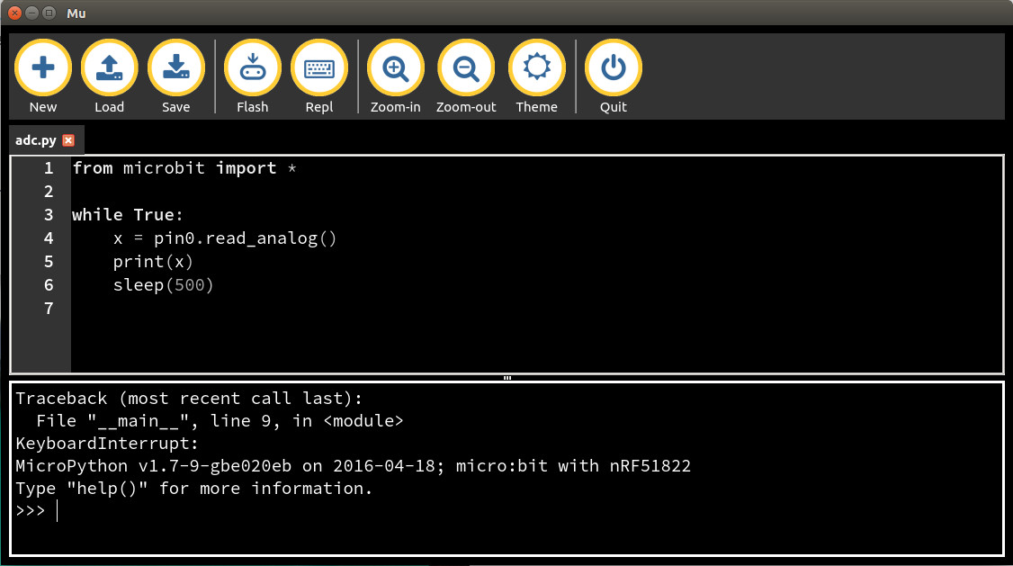
Figure 14 : Mu editor
from microbit import *

while True:
    x = pin0.read_analog()
    print(x)
    sleep(500)
Figure 15 : ADC test code
from microbit import *

clap=False
while True:
    peak=0
    display.set_pixel(0,0,0)
    print("START")

    while (peak < 1000):
        peak = pin0.read_analog()

    start_time = running_time()
    display.set_pixel(0,0,9)

    while (peak > 900):
        peak = pin0.read_analog()

    sleep(100)

    while (peak < 900 and ((running_time() - start_time) < 3000)):
        peak = pin0.read_analog()

    stop_time = running_time()
    display.set_pixel(0,0,0)

    delay_time = stop_time - start_time
    print(delay_time)

    if ((delay_time > 100) and (delay_time < 2000)):
        clap = True

    if clap:
        print("CLAP")
        clap = False
Figure 16 :Clap test code
Finally, some really nice examples and tutorials on using MicroPython and the Micro:bit can be found here: (LINK). The next item to test was the I2C interface using a simple I2C gpio expander, as shown in figure 17, purple wire is SCL and blue wire is SDA. The I2C address for this IC is 0x38, test code is shown in figure 18, simple turn-on / turn-off test. All worked.
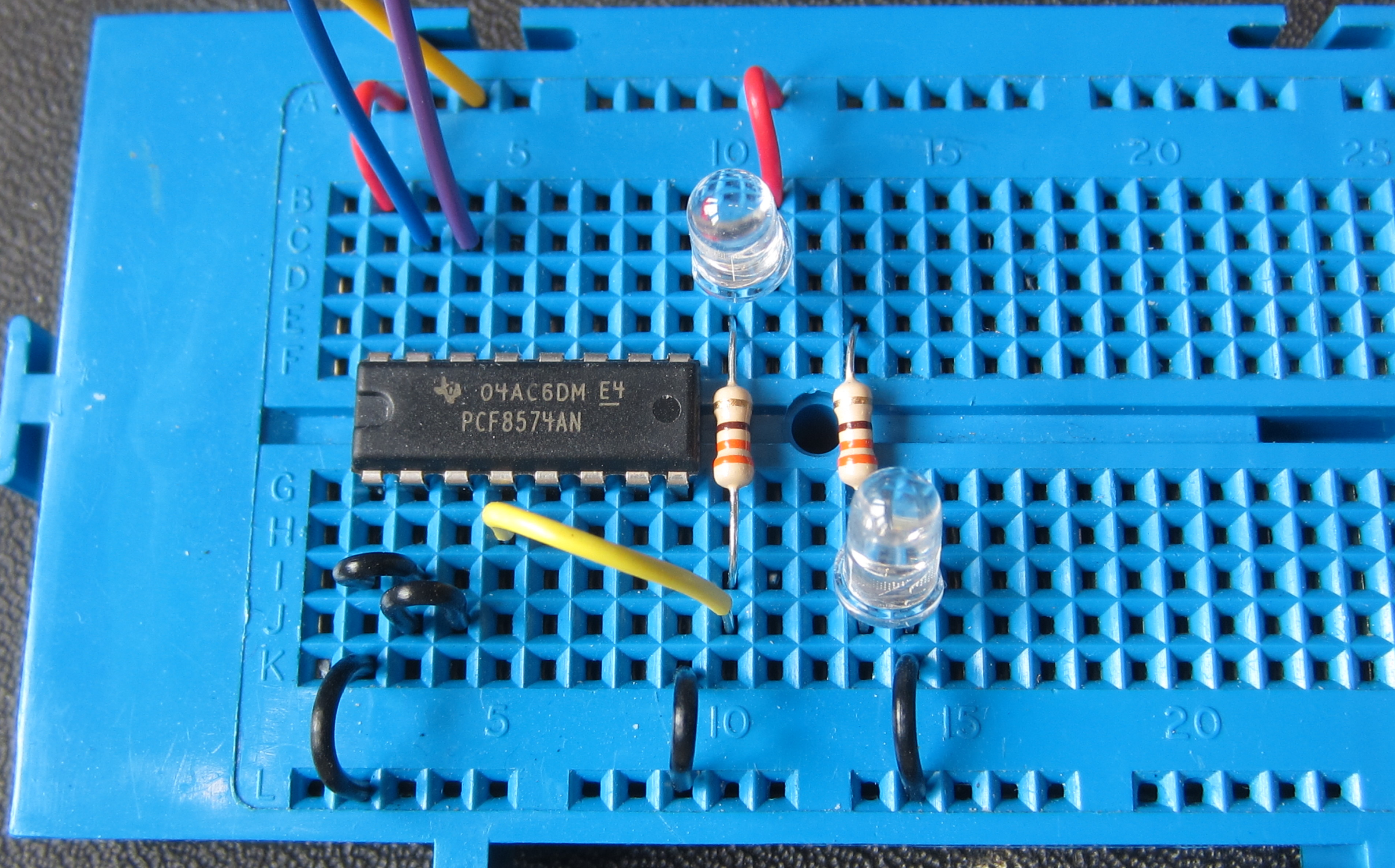
Figure 17 : I2C gpio expander test circuit
#Fixed ON/OFF
from microbit import *

addr = 0x38

display.show(Image.HEART)
sleep(500)
display.clear()

while True:
    i2c.write(addr, b'\x00', repeat=False)
    display.set_pixel(0,0,0)
    sleep(500)

    i2c.write(addr, b'\xFF', repeat=False)
    display.set_pixel(0,0,5)
    sleep(500)
#Button controlled ON/OFF
from microbit import *

addr = 0x38

display.show(Image.HEART)
sleep(500)
display.clear()

while True:
    if button_a.is_pressed():
        i2c.write(addr, b'\x00', repeat=False)
        display.set_pixel(0,0,0)
    elif button_b.is_pressed():
        i2c.write(addr, b'\xFF', repeat=False)
        display.set_pixel(0,0,5)
    else:
        sleep(100)
#Max speed ON/OFF
from microbit import *

addr = 0x38

display.show(Image.HEART)
sleep(500)
display.clear()

while True:
    i2c.write(addr, b'\x00', repeat=False)
    i2c.write(addr, b'\xFF', repeat=False)
Figure 18 : I2C gpio expander test code
Max On-Off gpio switching speed is approximately 900us i.e. a frequency of 1.1KHz and a pulse width of 450us, therefore, I2C is running at the default 100KHz clock speed, perhaps could be increased in software? Last test is digital inputs and outputs. Digital inputs to the Micro:bit include the two bumper switches at the front of the robot, these will be attached to pins 6 & 7 and can be tested using the following code:
from microbit import *

while True:
    left = pin6.read_digital()
    right = pin7.read_digital()
    message = str(left) + " " + str(right)
    print(message)
    sleep(500)
Again all ok, can use either +4.5V or 3.3V as voltage source since pull-up resistor is 100K i.e. very small current. Digital outputs from the Micro:bit include the four motor control signals, these will be attached to pins 13/14 and 15/17 and can be tested using the following code:
from microbit import *

while True:
    pin13.write_digital(1)    #all stop
    pin14.write_digital(1)
    pin15.write_digital(1)
    pin16.write_digital(1)

    sleep(10000)              #wait 10 secs

    pin13.write_digital(1)    #forwards
    pin14.write_digital(0)
    pin15.write_digital(1)
    pin16.write_digital(0)

    sleep(10000)              #wait 10 secs

    pin13.write_digital(0)    #backwards
    pin14.write_digital(0)
    pin15.write_digital(0)
    pin16.write_digital(0)

    sleep(10000)              #wait 10 secs
Some of the outputs can also be used as 'analogue outputs' i.e. pulse width modulated (PWM). These could be used to control the speed of the motors. Unfortunately these only seem to work on the Analogue pins, which are either used to read analogue inputs or are used to control the LED display panel. The code below does work, but because of pi sharing these pins not sure who useful this will be. Also the period function does not seem to work and not sure what the units are for the function write_analog(), thought it was a percentage on-time?
from microbit import *

pin15.write_digital(1)       #all stop
#pin0.set_analog_period(50)  #doesn't seem to do anything?

while True:
    pin0.write_analog(120)
    sleep(2000)              #wait

    pin0.write_analog(240)
    sleep(2000)              #wait

    pin0.write_analog(360)
    sleep(2000)              #wait

    pin0.write_analog(480)
    sleep(2000)              #wait

    pin0.write_analog(600)
    sleep(2000)              #wait

    pin0.write_analog(800)
    sleep(2000)              #wait
Stop and a pause, PCB is getting a little complex, too many jumpers that perhaps will never be used, therefore, simplified the design a little. Also running out of pins, really want to avoid using the pins that are shared with the LED panel/display. Come to conclusion you can't have it all, the micro:bit supports a lot of stuff, but you can't use it all at the same time e.g. can't see a function to turn off the LED display so that you can use these pins for other functions. Therefore, need to decide what is core and put the nice to haves to one side:
Speed control, this needs to be a fire and forget function, so will use pins 1 and 2 (single purpose pins). As pin 0 is hard-coded as the speaker output, this leaves pins 4 and 10 for the LDR / operational amplifier driven signals. At present can't see how to switch between the LED and Analogue functions i.e. when you read the analogue in you also change the LEDs. Simple solution is to use a current limiting resistor i.e. 100 ohms, and hope for the best. This sort of works, but you can't pull this input down to 0V as i guess its fighting the LED driver output.
Finally got round to finishing the PCB layout as shown in figures 19 ans 20. Kept it chunky to simplify prototype etching in-house, or if others wish to build it. Could be a bit smaller, but at 80mm x 110mm isn't too bad for version 1, obviously its gigantic compared to the surface mount version, but this pin-through-board version can be assembled at home. Also updated the 3D model, as shown in figure 21, made the front bump sensors look a little more Roachy, added an ultrasonic sensor mount and rear legs to mount the rear bump sensors. Still need to work on the face. Top shell will need to be updated, but need to see how the micro:bit and PCB fit first. PCB designed to take the standard expansion connector/pcb, such that the micro:bit could be removed and plugged into another system or bread-board.
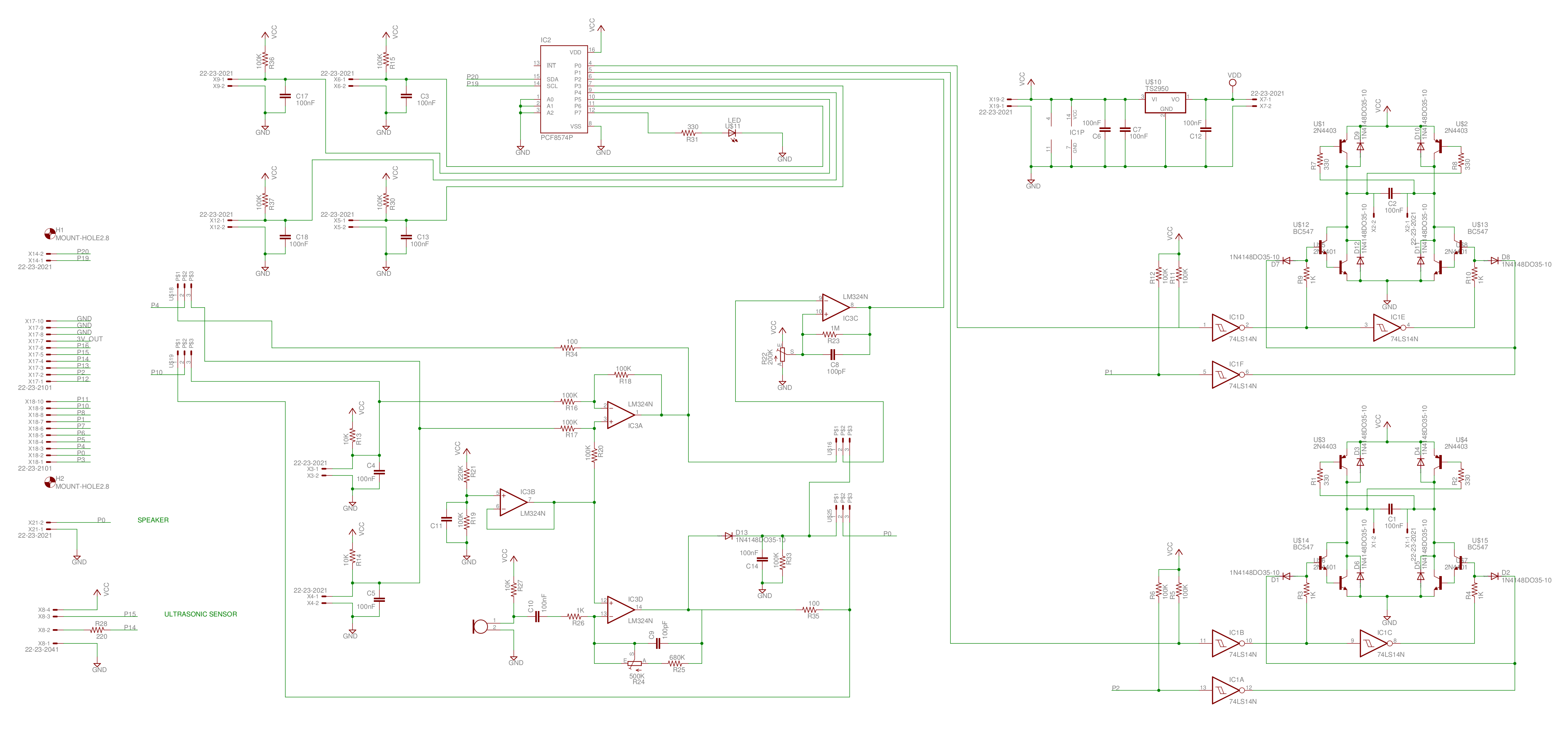
Figure 19 : Schematic V1.1
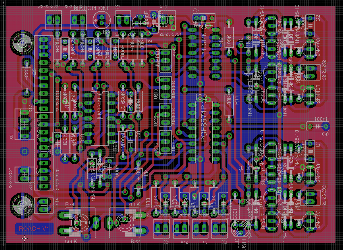
Figure 20 : PCB V1.1
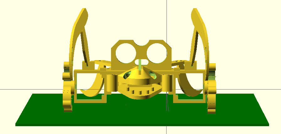
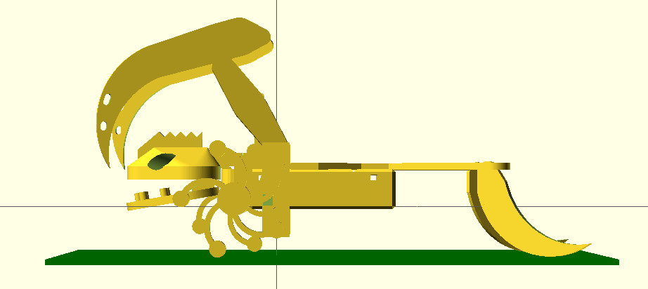
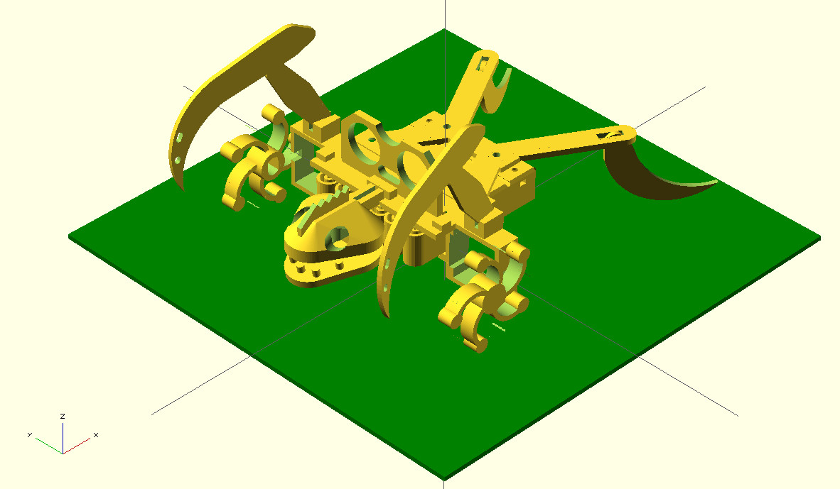
Figure 21 : 3D model V1.1
Whilst the PCB is being made, a pause to consider the robots code. Basic motor control, speed control is simple. A more complex problem is navigation (how to get from A to B) and localisation (where am i). To help with this the microbit has two sensors: an accelerometer and a compass. In theory you can use the accelerometer to calculate the distance travelled, this should be 'simple', basically the accumulation of the acceleration values at fixed time intervals will give a value proportional to velocity, may need a bit of scaling etc. Then if you know the velocity and you can measure the passage of time you get distance i.e. if you integrate acceleration with respect to time you get velocity, if you integrate velocity with respect to time you get distance. To test the microbit's sensor used this code (also tested for negative g):
from microbit import *

display.show(Image.HEART)
sleep(500)
display.clear()

xmax=0
ymax=0
zmax=0

count = 0

while True:
    x = accelerometer.get_x()
    y = accelerometer.get_y()
    z = accelerometer.get_z()
    message = "X=" + str(x) + " Y=" + str(y) + " Z=" + str(z)
    print(message)

    sleep(0.5)

    if x>xmax:
        xmax=x
        message = "XMAX=" + str(x)
        print(message)

    if y>ymax:
        ymax=y
        message = "YMAX=" + str(y)
        print(message)

    if z>zmax:
        zmax=z
        message = "ZMAX=" + str(z)
        print(message)

    sleep(0.5)

    count = count +1

    if count > 30:
        xmax=0
	ymax=0
	zmax=0

	count = 0
First mistake, forgot to take gravity into consideration i.e. when standing still you don't get a zero acceleration value in the z axis, also need to consider the microbit will not be perfectly flat/level, so X & Y axis will vary. However, this isn't a big problem, can record initial valves at power-up, also could assume the robot is level at the start i.e. not on a hill etc. To see if this techniques works on this robot, going to have to record a data set with the robot moving, plot some graphs to see what the signal/noise looks like. Fortunately i've just finished making the PCB as shown in figure 22. As always works perfectly until i start to test it, i'm sure it will work first time :)
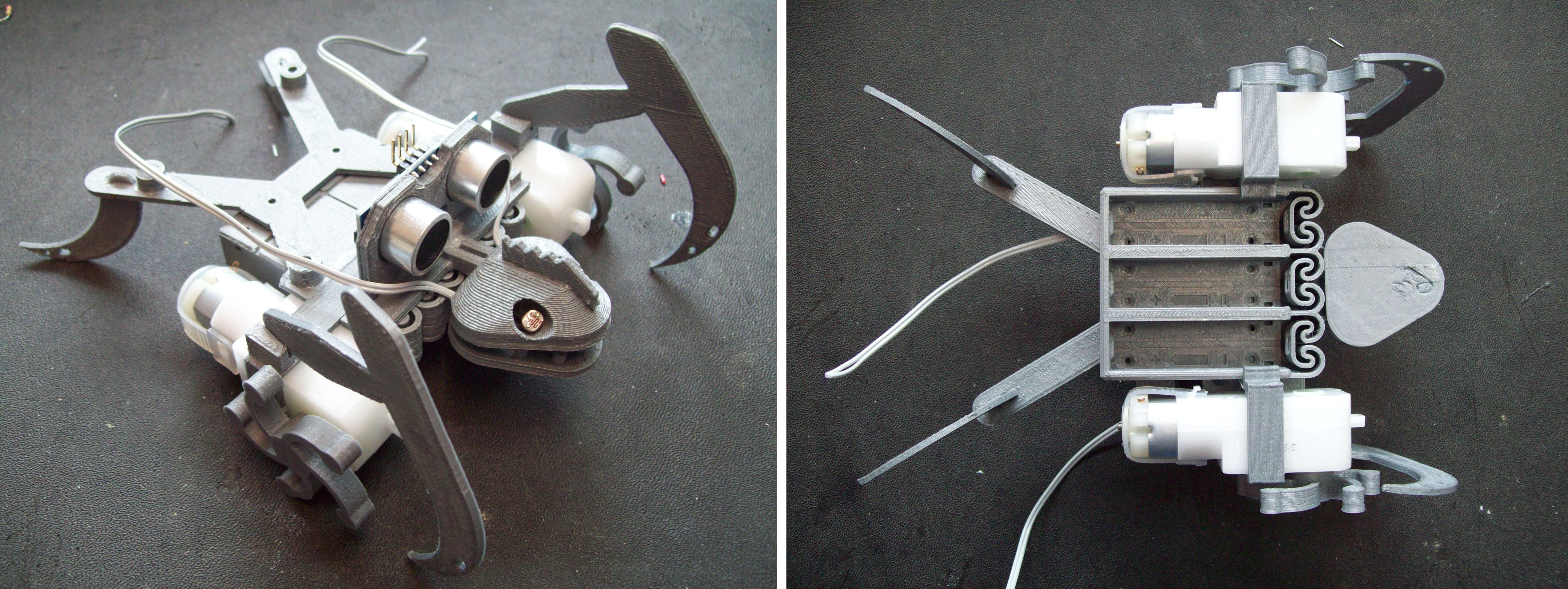
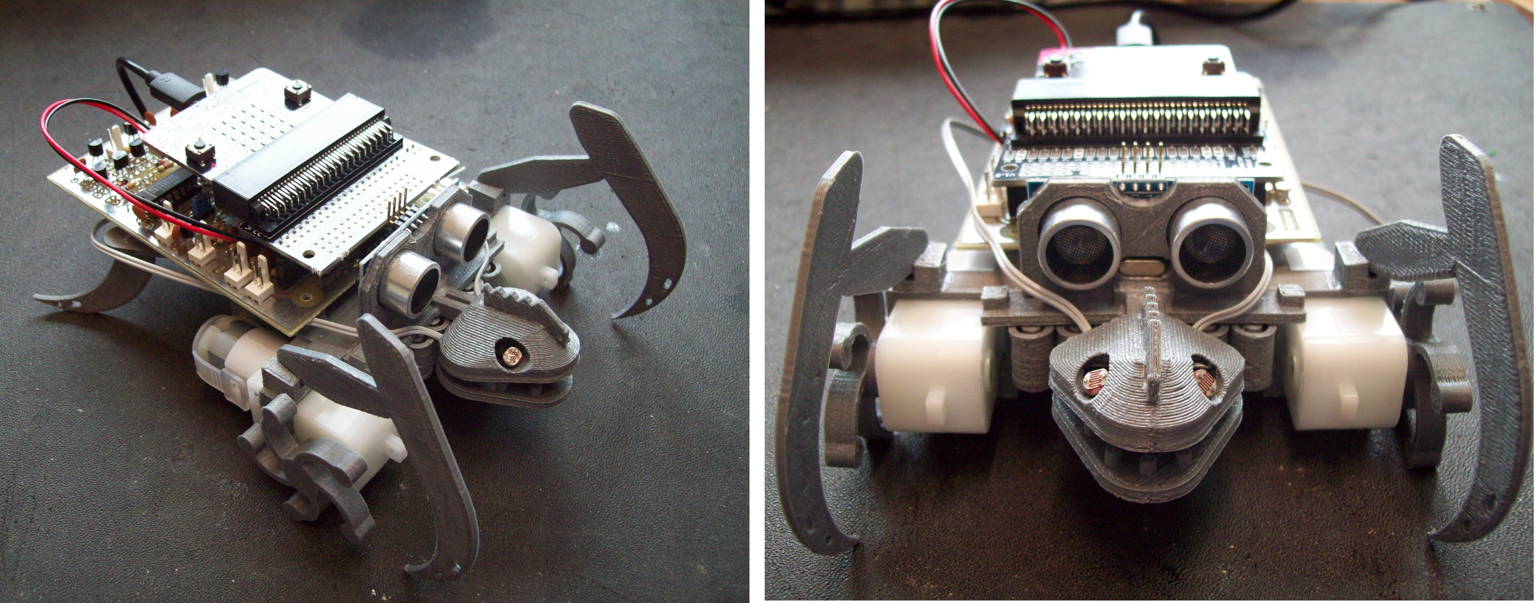
Figure 22 : assembled Roach V1.1
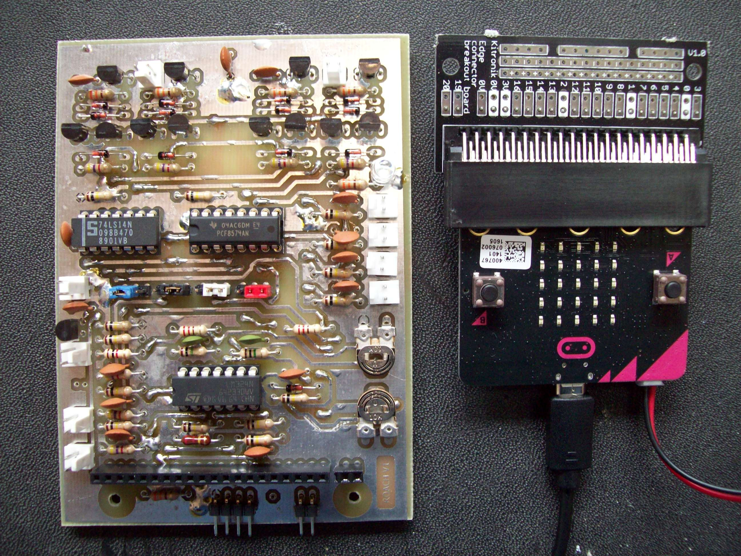
Figure 23 : PCB V1.1
The ultrasonic sensor position may look like its going to get interference from the body work, but i tested the sensor using a signal generator and a scope and it does work fine, which i found surprising. Improvements: ultrasonic sensor and speaker sockets, a little tall, short term solution, go to angled version, but need to find an alternative. Microbit edge connector, unfortunately the pcb that comes with the socket is not double sided, therefore, soldering the pin strip onto the bottom layer is a bit tricky, still like the look / idea of allowing the microbit to be unplugged, but need an alternative solution / pcb. Also been thinking about the supply voltage, 4.5V may be a little low when you consider the voltage drops across the transistors, may need 6V i.e. 4 cells. This isn't too bad if i can get a 2 x 2 battery pack, could even go to 9V i.e. 6 cells, 3 x 2 battery pack, however, same dangers as with the Zergling, need to keep the centre of gravity under/between the drive wheels. Also, increasing the voltage means i would need a +5V regulator, again not a bad idea from a noise point of view.
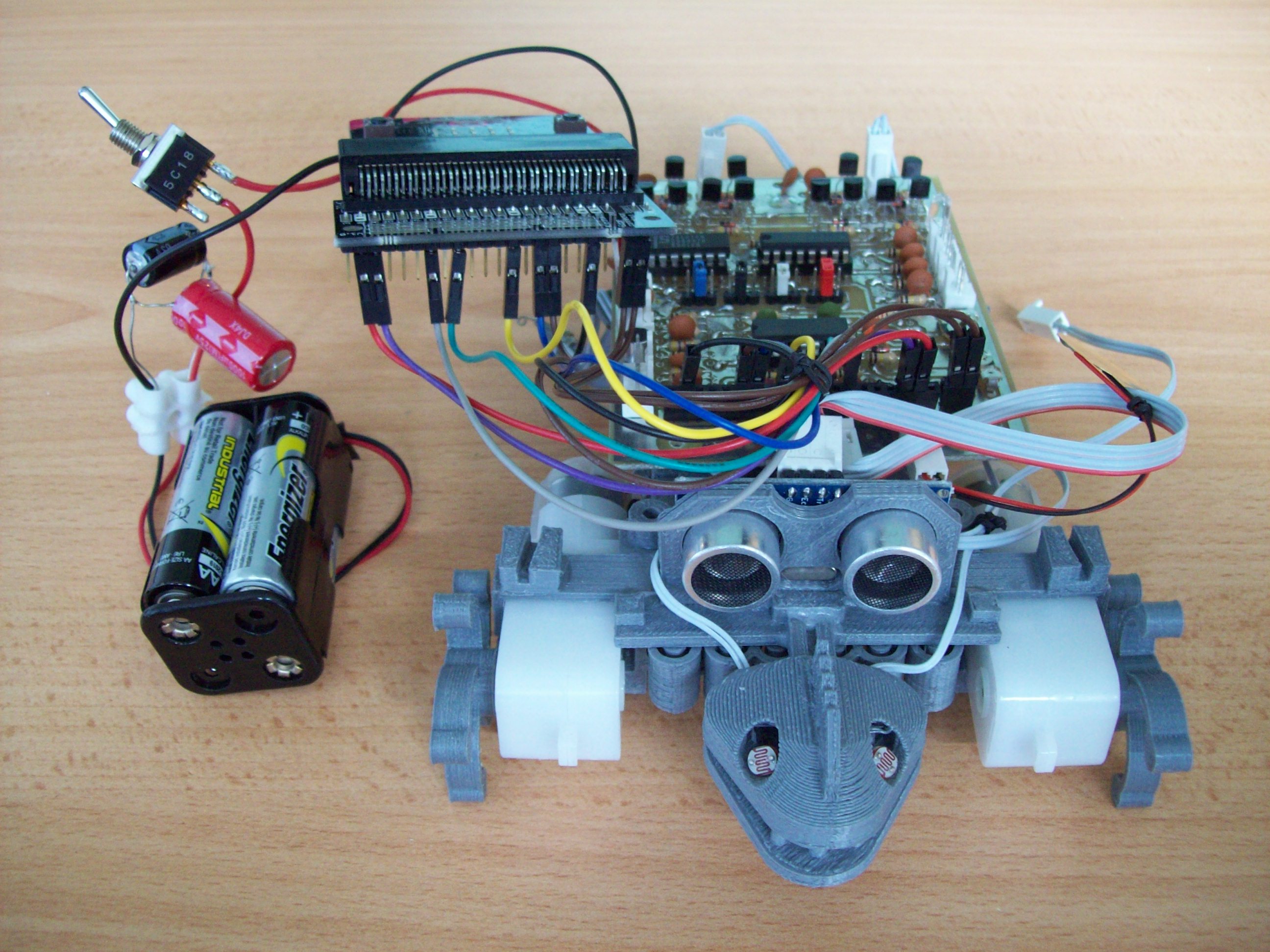
Figure 24 : prototype 1
Prototype 1 up and running, well walking, as can be seen in this video, forwards and backwards, fast, medium, slow and stop: (LINK). A little messy used extension leads to connect the microbit, makes debugging a lot easier i.e. can get a scope/multi-meter onto the board. Also using an external battery pack / power supply as they are easier to connect. As always with the first prototype as few issues:
Advice on Micropython github issues (LINK) was to use display.off(), this helped, but i think the microbits on-board LEDs were still loading the LDR circuit. Had a play around, looks like you need a low impedance driver, the simple potential dividers used by the LDRs can't drive these inputs low. Adding an operational amplifier follower stage seems to work, but again not sure whats connected to these pins, but it seems ok (confess this is not the way to design hardware). Just to be safe i put in a 200 ohms series resistor.
Currently using the same wire 'switches' as the Zergling, these are cheap, but as this will be used in schools want something a little more reliable, so will need to move to micro switches. The only down side is mounting i.e. incorporating the mechanical mechanisms into the 3D model.
This design was getting increasingly difficult to make, therefore, decided to take this work in the other direction: can you build an micro:bit robot using only off the shelf modules? This resulted in the Roach_V2 : Pet Roach v2.

This work is licensed under a Creative Commons Attribution-NonCommercial-NoDerivatives 4.0 International License.
Contact details: email - mike.freeman@york.ac.uk, telephone - 01904 32(5473)
Back