This is a motor speed control problem based around a perpetual marble lift. Normal programming examples focus on developing algorithms to solve a problem. This problem is a little different, the complexity here is due to the parallel nature of the real world, highlighting the limitations of some software based solutions when learning to program. To control the speed of the motor a simple PID controller is implemented in software i.e. a control signal based on the motor's speed sensor. This sensor's frequency is proportional to the motor's speed, therefore, the processor has to measure the period of this signal. However, whilst it is doing this it can not update the signal controlling the motor. These types of problems introduce the ideas of deadlines, parallel processing and sharing data etc. In addition to these problems the program has to also count the number of marbles that have passed down the chute and display this information on the LCD and LED displays. This requires access to shared hardware, I2C bus and GPIO pins. To add a further level of complexity both the motor control and speed sensor can be implemented as either an analogue or a digital signal. An interesting programming problem :).
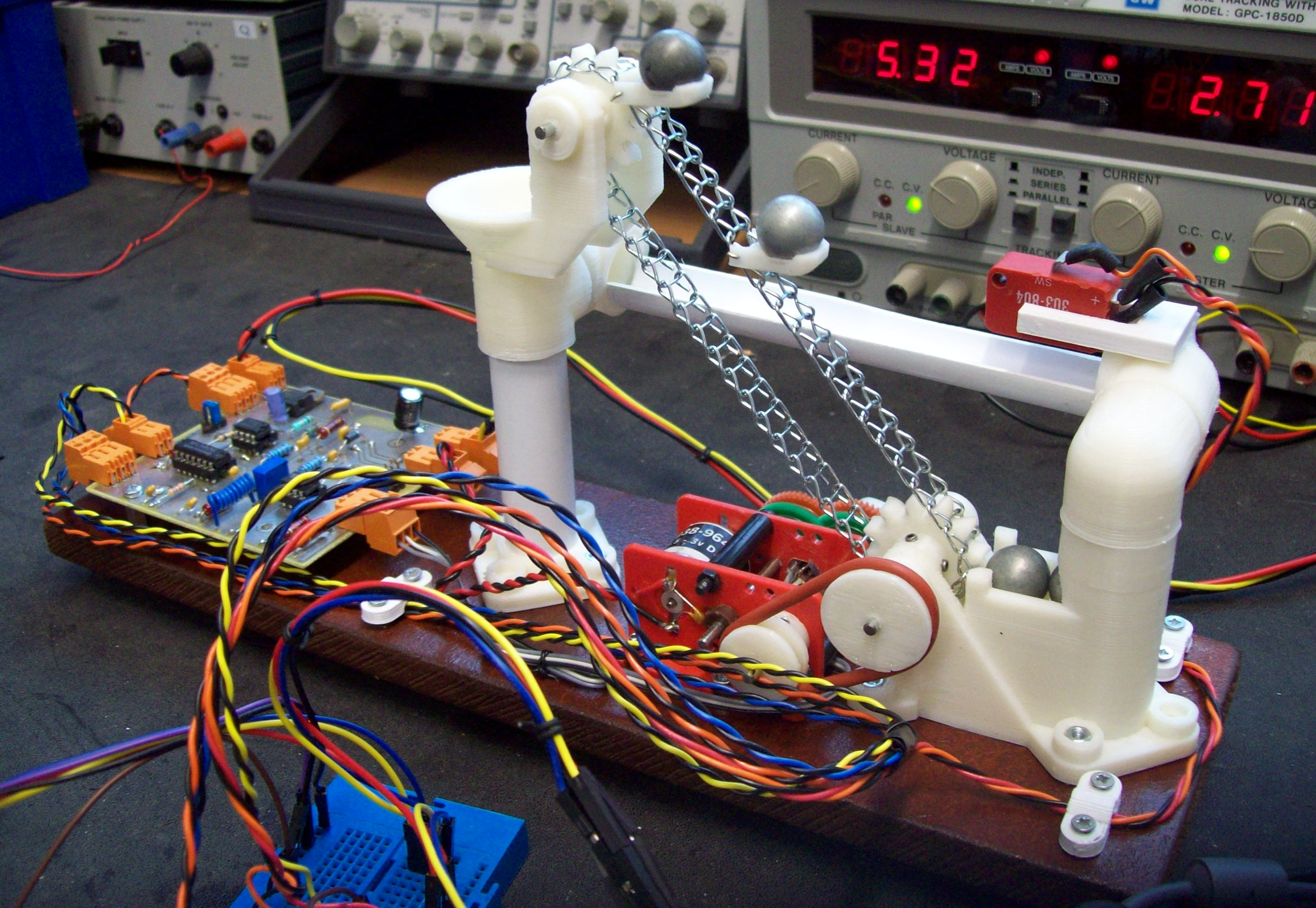
The lower tower holds four ball bearings (K'nex), a small D.C. motor connected via a pulley system drives a chain and bucket lift, raising the ball bearings to the top tower, where upon they drop into a funnel and roll back under gravity to the start, as shown in figure 1. The chain / drive shafts were sourced from Rapid, the top tower's upright is made from main's trunking, the ramp's 'guttering' is made from the same trunking, just hack-sawed in half, everything else is 3D printed. Its been a while since i designed this 3D model, so not sure this zip has all the design files / components, but it all i can find at present (Link). As normal, holes may need clearing with a drill / reamer etc, otherwise there will quite a bit of friction on the drive shafts.
Figure 1 : Marble lift
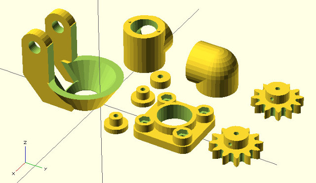
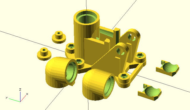
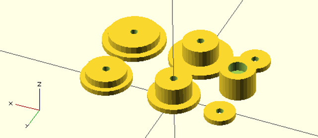
Figure 2 : 3D model
This hardware was originally designed as a project for the first year module Programming of Micro-controllers (PROM), however, it soon became apparent that manufacturing tolerances would be a problem i.e. creating 50 'identical' systems. This was mainly due to variations in drive shaft alignment, bearing friction and motor performance. The original idea was to develop a motor speed controller problem. The aim was to maintain a fixed motor speed, adjusting the motor's control signals to compensate for variations in load i.e. the number of ball bearings being lifted. Although this may seem perfectly possible the actual increase in load owing to the increasing number of steel balls was very small when compared to variations in 'background' load (friction) in the drive chain i.e. it was difficult to observe a significant reduction in speed as the number of ball bearings was increased. Perhaps we need bigger ball bearings, maybe next year.
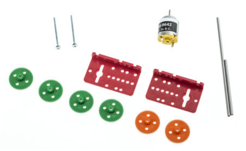
Figure 2 : Motor & gearbox kit
The D.C. drive motor was sourced from a previous module (had a box of 50), Como Drills DC Geared Motor, 1.5 - 3V, approx £5 each, sourced from RS or Rapid, as shown in figure 2 (Link). These motors are quite simplistic, externalising the main components i.e. motor and gearbox. One of the main reasons for selecting these motor's (apart from they were free) was that it was quite easy to add a sensor to measure the speed of the motor. The sensor used was a OPB608 (Link), an infra-red transmitter (LED) / receiver (photo-transistor) housed in a single package. This sensor was mounted in the motor such that the first drive gear was approximatly 1-2mm in front of the sensor. As the gear wheel moved past the sensor the four holes in the gear pass over the sensor, therefore, varying the ammount of infra-red light reflected back to the photo transistor i.e. no hole = more light, hole = less light. To try and increase the difference between these two states the holes were enlarged slightly i.e. to reduce the amount of reflected light, and the solid part of the gear (face) was painted white or silver i.e. to increase the amount of reflected light. The assembled sensor and gearbox is shown in figure 4.
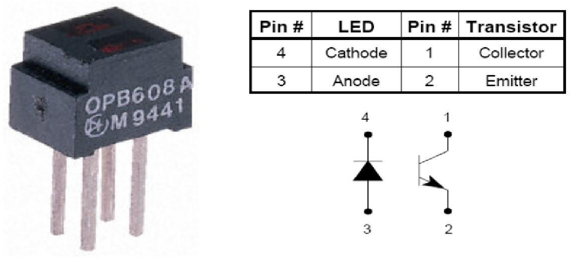
Figure 3 : Infra-red sensor
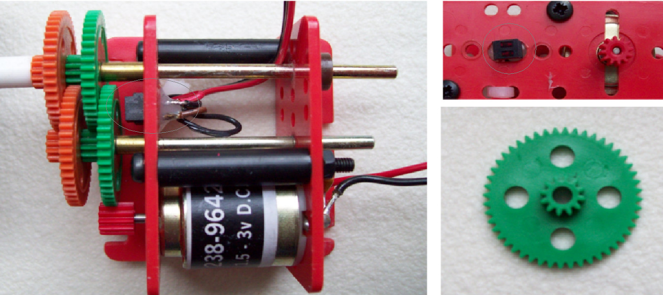
Figure 4 : Assembled motor + sensor
The signal generated by the OPB608 sensor is Sine wave in natural + a D.C. offset, therefore, not that useful as far as the Raspberry Pi is concerned. To transform this signal into something a little more digital it was passed through an analogue comparator and a simple low pass filter to remove any spike or high frequency noise, as shown in figure 5. The LM311 comparator (Link), acts as an analogue Schmitt trigger, its variable resistor defines the voltage threshold for a hole i.e. to the sensor output voltage for a hole will be the peak of the Sine wave. This signal is then passed through a 7414 NOT gate (Link), a digital Schmitt trigger, to generate a 'hard' digital '1' or '0' before being passed through a low pass filter. The low pass filter removes any high frequency noise generated by the motor or other sources of electrical interference, before being finally 'squared' by a final 7414 NOT gate. The resulting output for the motor running at a slow and fast speed is shown in figure 6. This 'clean' signal can now be used by the Raspberry pi, however, it will need to be level shifted from +5V downto +3V, this is done by a simple potential divider e.g. two 10K resistors, to give 2.5V, or a series resistor e.g. 330, to limit input current.
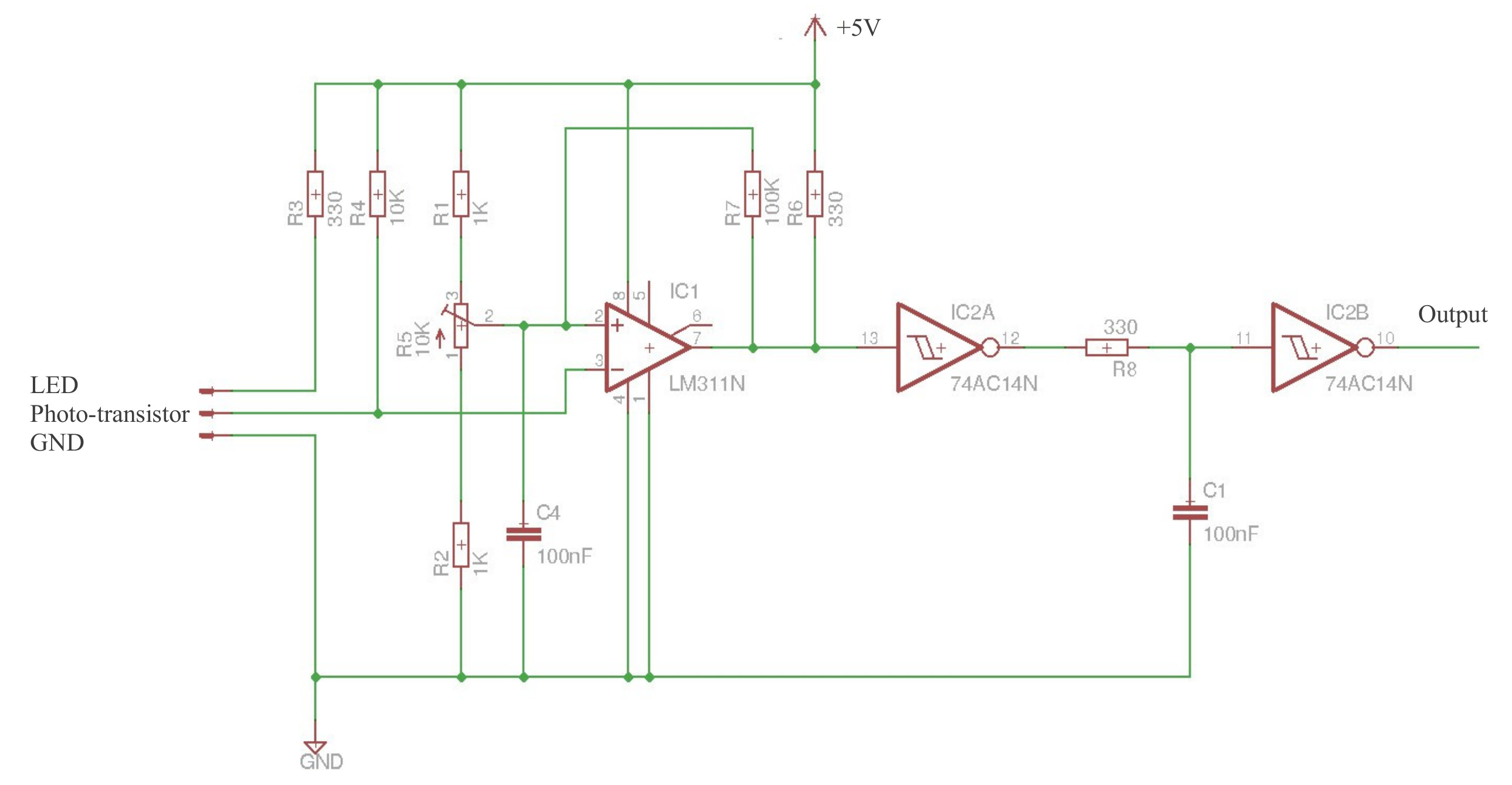
Figure 5 : 'Squaring' circuit
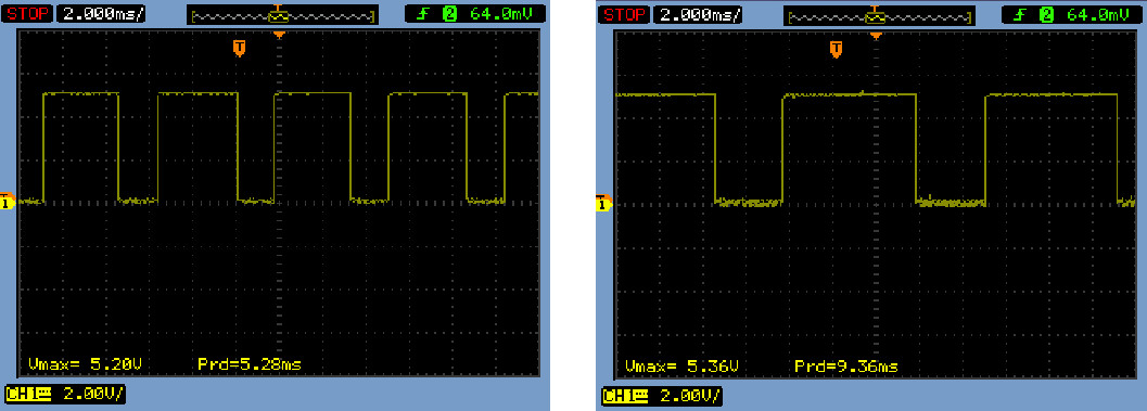
Figure 6 : Speed sensor waveform, fast (left), slow (right)
From figure 6 it can be seen that the sensor's period varies from 5ms for a 'fast' motor speed, down to 10ms for a slow motor speed. The number of pulses generated per output shaft revolution is determined by the number of gears used in the gearbox i.e. will vary from 16 to 16384 pulses per revolution. As previously stated the aim of this project was to implement a motor speed controller, therefore, to make this task a little more tricky, rather than using this digital signal directly to measure the speed of the motor this signal was to be converted into an analogue signal using a frequency to voltage (F2V) converter. There are a number of different F2V converters, but one of the simplest to build is based on the LM2917 (Link), as shown in 7. The input signal for this circuit is driven by the output of figure 5. For the range of frequencies this sensor produces the standard F2V circuits seem to work perfectly well, producing a nice clean analogue voltage proportional to the motor's speed.
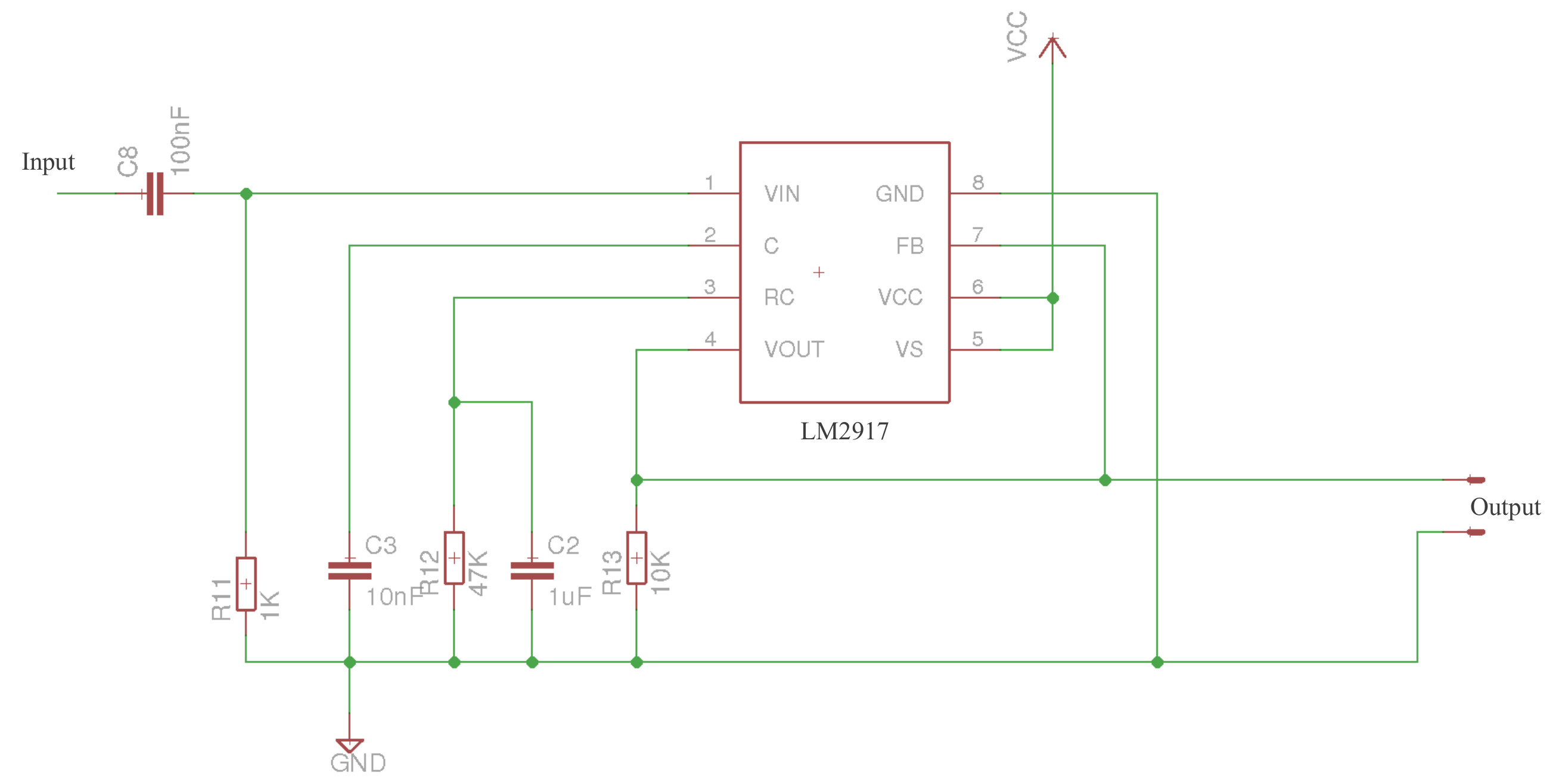
Figure 7 : Frequency to voltage converter
The motor only needs to turn in one direction i.e. lift the marbles, so a simple common collector driver is used, as shown in figure 8. To limit the drive voltage / current a zener diode and poly-fuse are used (actually a 6V zener). The drive transistor is a Darlington pair to help reduce the required input base current and to drop a little voltage as the motor is rated at 3V. As always there is a flywheel diode and RC snubber to help remove transient spikes. The input and output of this drive stage can be configured using jumpers. On the input side you can select an analogue input or digital input. The digital input has both inverted and non-inverted forms. On the output side you can either connect the motor directly to the drive transistor or select one or more series resistors. The aim here was to add series resistors inline with the motor to help reduce its torque if needed. When controlling the motor either an analogue operational amplifier controller can be designed using the analogue signal from the LM2917, to directly drive the Darlington pair, or alternatively a digital signal can used, approximating analogue control using pulse width modulation, as shown in figure 9. The eagle files and PCB layout for this circuit is available here (Link).
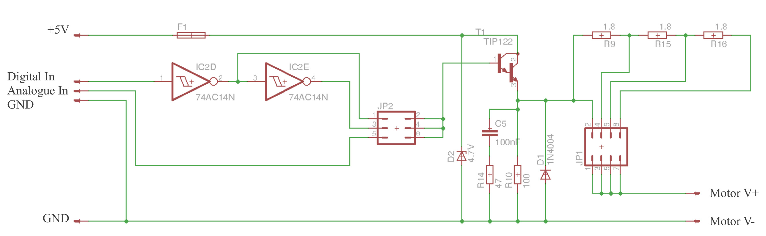
Figure 8 : Driver stage
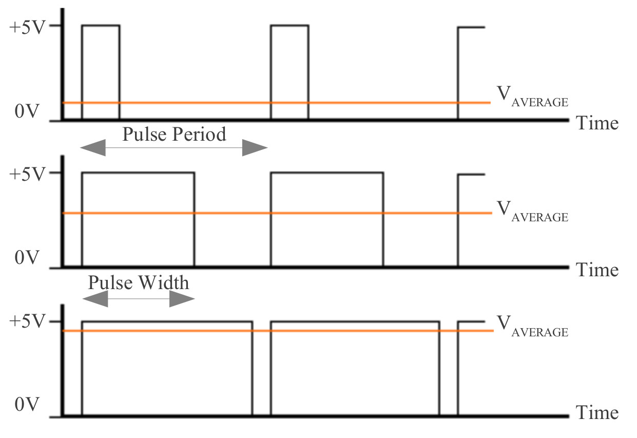
Figure 9 : Pulse width modulation (PWM)
To generate a PWM signal one of the GPIO lines on the Rapsberry Pi has been used. This is not the most stable PWM signals you will see, as its generated under software control, but, it does 'work'. The python code to test the motor is based on this example code (Link) as shown below. The output period is incrementally increased, then reset.
import time
import RPi.GPIO as GPIO

#IO
PWM_PIN = 14
PWM_FREQ = 50

GPIO.setwarnings(False)
GPIO.setmode(GPIO.BCM)
GPIO.setup(PWM_PIN, GPIO.OUT)

pwm = GPIO.PWM(PWM_PIN, PWM_FREQ)
pwm.start(0)

try:
  while True:
    for dc in range(0, 90, 5):
      pwm.ChangeDutyCycle(dc)
      time.sleep(0.5)

except KeyboardInterrupt:
	pass
pwm.stop()
GPIO.cleanup()
Figure 10 : PWM test code
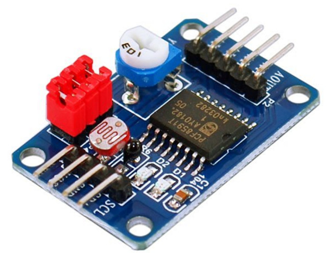
Figure 11 : PCF8591 ADC board
Now that the motor can be controlled the speed sensor can be tested. To interface the Pi to the analogue speed sensor signal i got a cheap PCF8591 board off Amazon (£1.99), a simple four channel, 8bit, I2C ADC, datasheet is available here: (Link). The python code to test code for this sensor is shown in figure 13, the recorded sensor values for a loaded and unloaded motor are shown in figure 12. As expected a little noisy and the relationship between duty cycle and speed is not that linear i.e. dead band to start and saturation at the top.
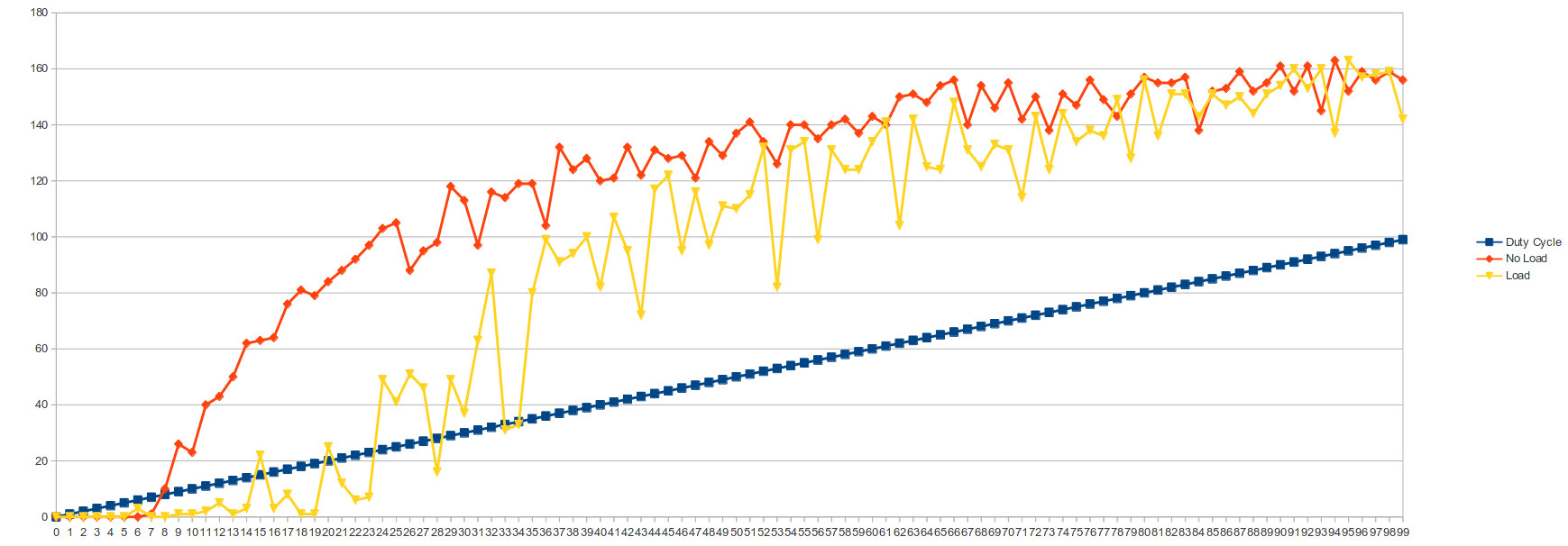
Figure 12 : Analogue sensor v duty cycle
import smbus
import time
import RPi.GPIO as GPIO

#IO
PWM_PIN  = 14
PWM_FREQ = 50
I2C_ADDR = 0x48

GPIO.setwarnings(False)
GPIO.setmode(GPIO.BCM)
GPIO.setup(PWM_PIN, GPIO.OUT)

pwm = GPIO.PWM(PWM_PIN, PWM_FREQ)
pwm.start(0)

bus = smbus.SMBus(1)
data_log = open("data_log.csv","w")

try:
  for dc in range(0, 90, 1):
    pwm.ChangeDutyCycle(dc)

    # ADC 0
    bus.write_byte(I2C_ADDR, 0x40)
    bus.read_byte(I2C_ADDR)
    data = bus.read_byte(I2C_ADDR)

    outputString = str(dc) + "," + str(data)
    print outputString

    data_log.write( outputString )

    time.sleep(0.5)

  data_log.close()

except KeyboardInterrupt:
	pass
pwm.stop()
GPIO.cleanup()
Figure 13 : Analogue sensor test code
In some respects the digital speed sensor is a little more tricky to process, in that the processor have to directly measure the period of the input signal. The python code to test this sensor is shown in figure 15, the recorded sensor values for a loaded and unloaded motor are shown in figure 14. Initially, tried to use the system time to calculate the period, but, later switched to raw count values, as i thought these would be a little more accurate. Again a little noisy, observing on the oscilloscope there was quite a bit of variation in the signals period, definitely needed a little more processing e.g. take multiple readings and use the median or mean. Initially the digital speed sensor's data does not look that promising, but if you ignore the very slow speeds you can see there is relationship between duty cycle and frequency.
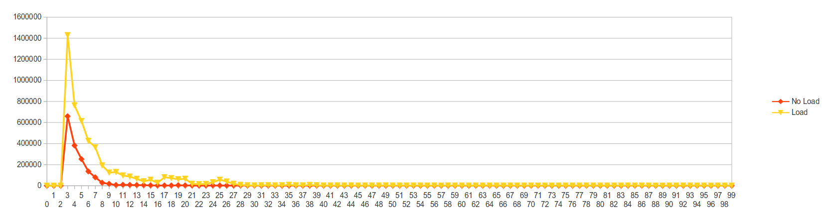
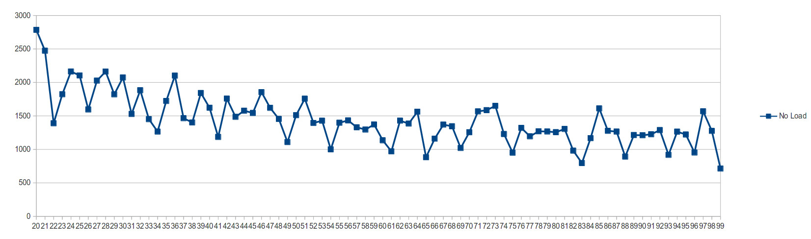
Figure 14 : Digital sensor v duty cycle
import smbus
import time
import RPi.GPIO as GPIO

#IO
PWM_PIN  = 14
PWM_FREQ = 50

SENSOR_PIN = 21

MAX = 1000000

GPIO.setwarnings(False)
GPIO.setmode(GPIO.BCM)
GPIO.setup(PWM_PIN, GPIO.OUT)
GPIO.setup(SENSOR_PIN, GPIO.IN)

pwm = GPIO.PWM(PWM_PIN, PWM_FREQ)
pwm.start(0)

bus = smbus.SMBus(1)
data_log = open("data_log.csv","w")

try:
  for dc in range(0, 100, 1):
    pwm.ChangeDutyCycle(dc)

    timeoutA=0
    while (GPIO.input(SENSOR_PIN)==0) and (timeoutA < MAX):
      timeoutA = timeoutA +1

    #pulse_start = time.time()

    timeoutB=0
    while (GPIO.input(SENSOR_PIN)==1) and (timeoutB < MAX):
      timeoutB = timeoutB +1

    timeoutC=0
    while (GPIO.input(SENSOR_PIN)==0) and (timeoutC < MAX):
      timeoutC = timeoutC +1

    if timeoutA < MAX and timeoutB < MAX and timeoutC < MAX:
      #pulse_end = time.time()
      #pulse_width = pulse_end - pulse_start

      pulse_width = timeoutB + timeoutC

    else:
      pulse_width = 0

    outputString = str(dc) + "," + str(pulse_width) + "\n"
    print outputString

    data_log.write( outputString )

    time.sleep(1)

  data_log.close()

except KeyboardInterrupt:
	pass
pwm.stop()
GPIO.cleanup()
Figure 15 : Digital sensor test code
To control the motor's speed i'm going to use a PID controller (Link), as shown in figure 16. The software realisation of this is based on this implementation (Link), basically the same with a couple of small changes. To keep things simple the first version will use the analogue speed sensor and the existing PWM library. Do confess its been a long time since ive looked at any control theory so this implementation will be very basic, i wouldn't consider my implementation as a reference example of how to design a PID controller e.g. selection of PID terms was just trial and error, needed to be a little more scientific. At the moment i've noticed i'm getting a lot of Integral windup. However, all python code can be downloaded here: (Link).
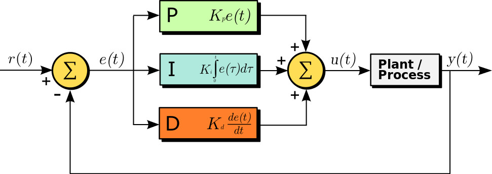
Figure 16 : PID controller
import smbus
import time
import RPi.GPIO as GPIO
import pid

SPEED = 30
P = 2
I = 0.1
D = 0

#IO
PWM_PIN = 14
PWM_FREQ = 50
I2C_ADDR = 0x48

GPIO.setwarnings(False)
GPIO.setmode(GPIO.BCM)
GPIO.setup(PWM_PIN, GPIO.OUT)

pwm = GPIO.PWM(PWM_PIN, PWM_FREQ)
pwm.start(0)
pwm.ChangeDutyCycle( 70 )

bus = smbus.SMBus(1)

controller = pid.PID(P,I,D)
controller.setSetPoint( SPEED )

try:
  while True:
    # ADC 0
    bus.write_byte(I2C_ADDR, 0x40)
    bus.read_byte(I2C_ADDR)
    sensor = bus.read_byte(I2C_ADDR)

    control_signal = controller.update( sensor )

    if control_signal < 0:
      control_signal = 0

    if control_signal > 100:
      control_signal = 100

    #outputString = str(sensor) + " " + str(control_signal) + " " + str(controller.PTerm) + " " + str(controller.ITerm)
    #print outputString

    pwm.ChangeDutyCycle( control_signal )

    time.sleep(0.001)

except KeyboardInterrupt:
	pass
pwm.stop()
GPIO.cleanup()
Figure 17 : PID test code
In addition to controlling the motor the Raspberry pi displays the speed of the motor and the number of balls that have been lifted using an LED bargraph and an LCD display. The LED bargraph has 24 LEDs, therefore, to drive all these outputs three I2C PCF8574 GPIO expanders (Link) have been used, as shown in figure 18. The Eagle schematic and PCB can be downloaded here: (Link), the python test code can be downloaded here: (Link).
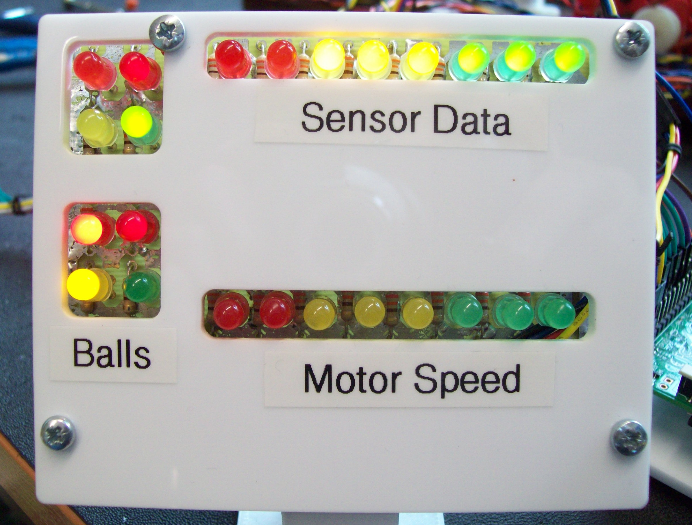
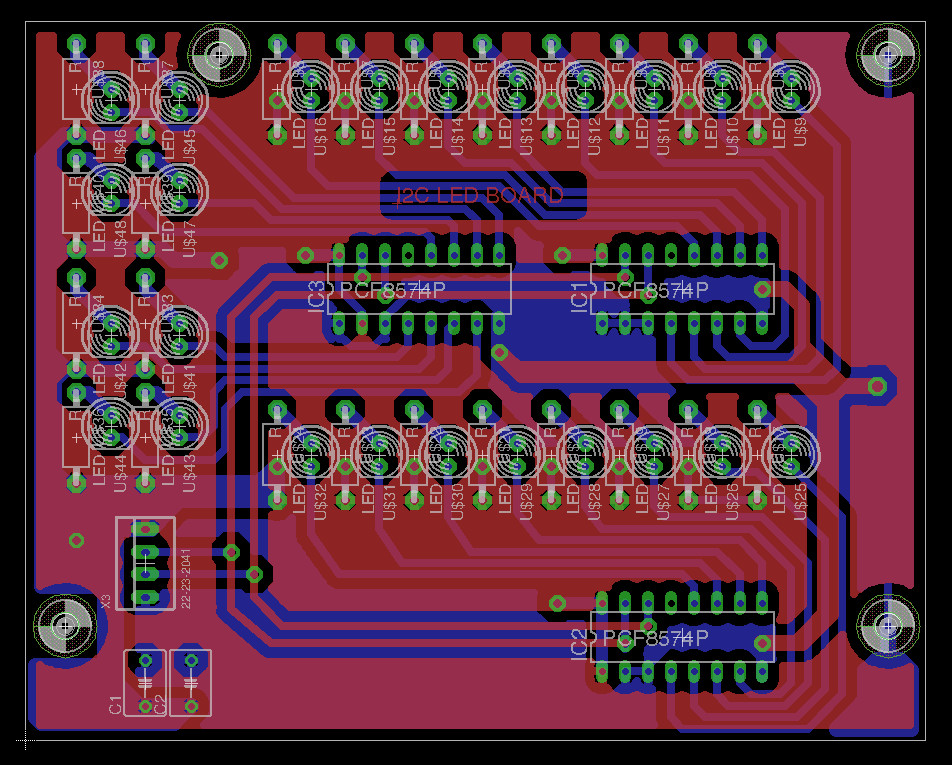
Figure 18: LED display
Ball counting is implemented by a simple inductive microswitch i.e. no moving parts, detects a iron objects. The only tricky bit is getting the distance between the sensor and the ball just right i.e. the gap needs to be about 1mm. The output signal from this sensor is used to trigger an event (interrupt) on the Raspberry Pi. The python code to implement this is shown in figure 20. This count value is then displayed on a LCD display. The python code to control the display was copied from (Link). The LCD module was then mounted in a simple stand (Link).

Figure 19: Inductive microswitch
#Ball sensor
BALL_SENSOR = 12

count = 0

def pin_event( pin ):
  global count
  count = count + 1
  lcd_string("Ball Count",LCD_LINE_1)
  lcd_string(str(count),LCD_LINE_2)
  return;

GPIO.setup( BALL_SENSOR, GPIO.IN, pull_up_down = GPIO.PUD_UP )
GPIO.add_event_detect( BALL_SENSOR, GPIO.RISING, callback=pin_event, bouncetime=500 )
Figure 20: Ball event code
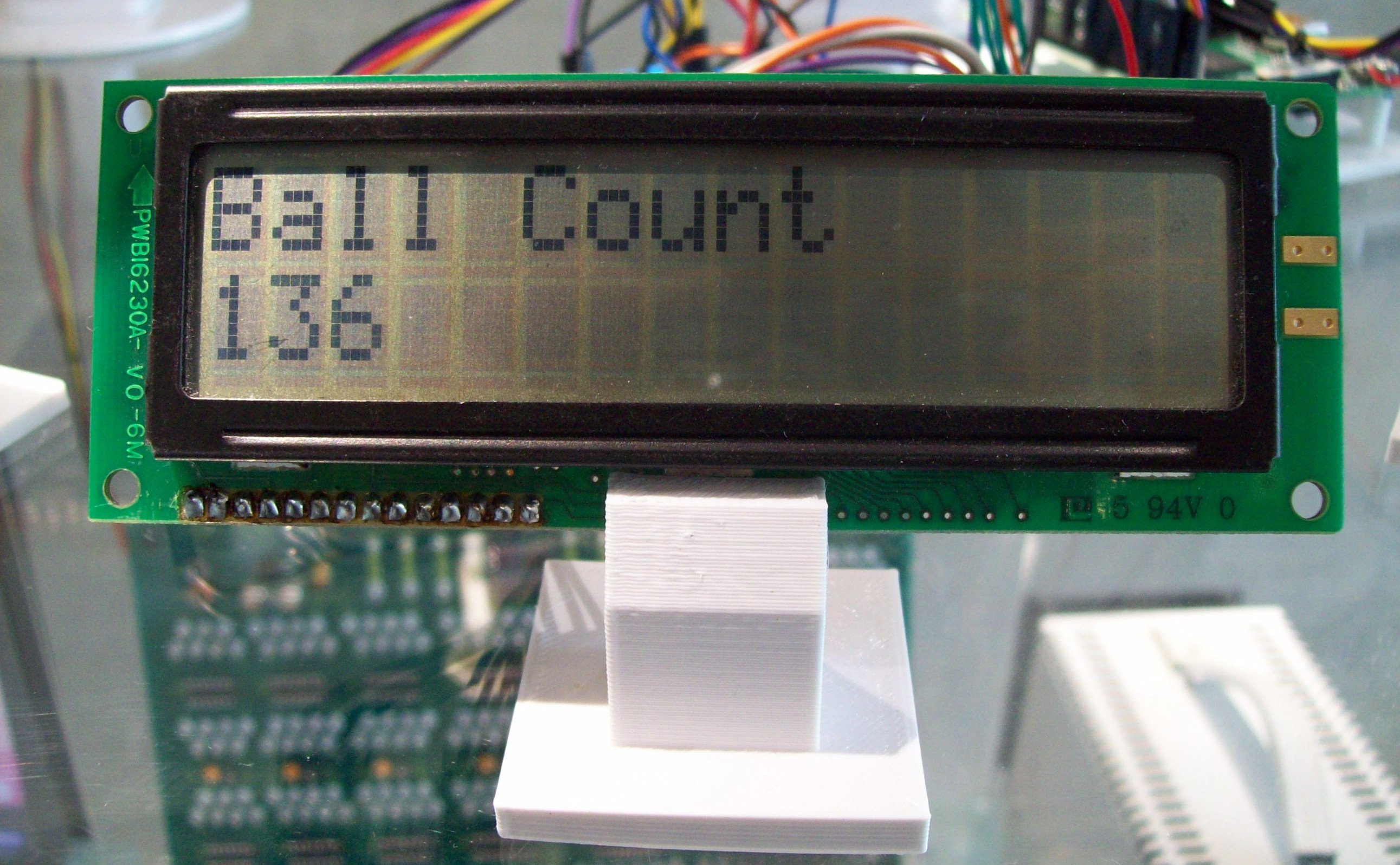
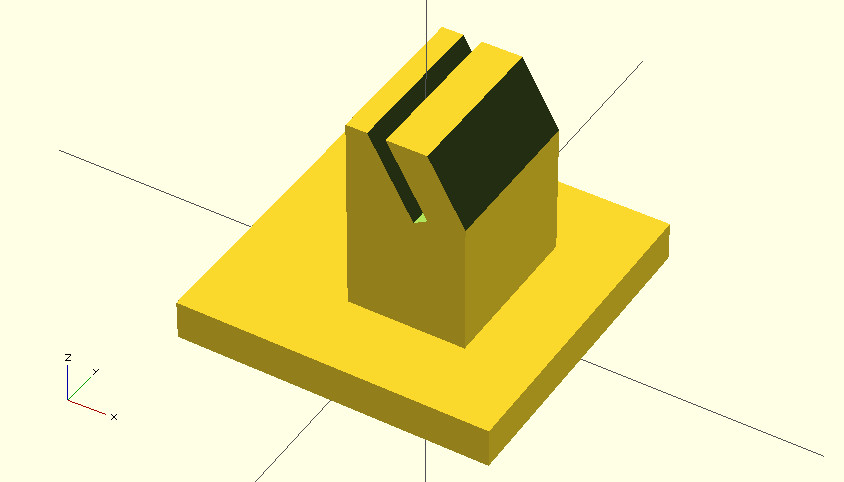
Figure 21: LCD and stand
The basic system works, a short video of the machine in action (Link), work on hold for the moment, when i get time will look into tuning the PID controller. Also looking to add some parallelism, which was the original aim, split the functionality across multiple processes, or use the multi-thread library (Link).

This work is licensed under a Creative Commons Attribution-NonCommercial-NoDerivatives 4.0 International License.
Contact details: email - mike.freeman@york.ac.uk, telephone - 01904 32(5473)
Back