MicroMouse is a annual competition held in Birmingham (HomePage) for small autonomous robots. Its aim is to promote Engineering in all its forms, mechanical, electrical, computing etc, in both Schools and Universities. The competition is divided into a number of different events (listed below) with categories for schools, juniors and seniors.
The aim for 2013 is to enter three robots, competing in the maze solver, line follower and drag race events. To save time two of these robots are based on existing platforms, modified to allow them to enter these events. As these robots use existing chassis they have a number of problems/ limitations e.g. difficulties in mounting sensors, motors etc, therefore these will be used as prototypes, to allow initial research into what the ideal robot requirements are. The third robot will build upon this research, designed specifically for the Maze solving event.
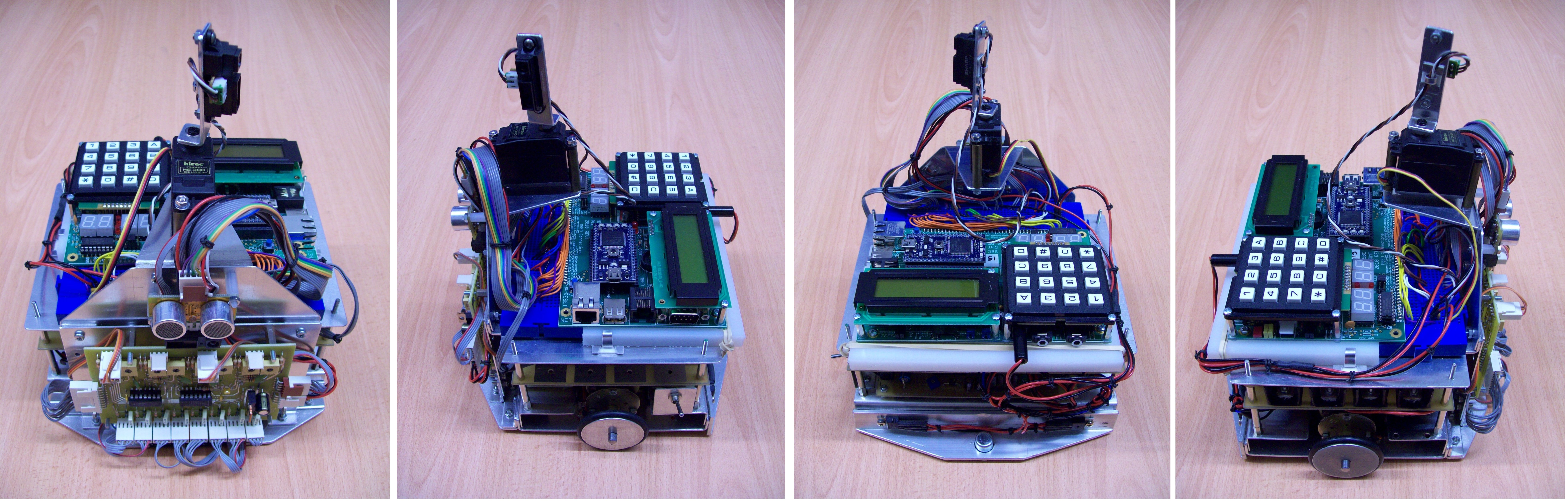
Figure 1.0 : RoseBud
This robot is based on Bud (Link), who in a previous life was a prototype for a robo-cup football team (Link). To convert Bud into RoseBud a significant amount of 'trellacing' had to be added to allow line sensors and their interface circuit to be mounted. RoseBud meets the competitions size regulations for all events, however, its a bit on the large size and would have great difficultly turning in the maze, therefore, it will be entered for the line following and drag race events.
For the line following event eight infra-red TX/RX sensor modules have been mounted on the front cross beam. Ideally these would be mounted slightly further forwards i.e. to give the robot more time to react to sharp corners >=90 degrees, however, this would exceed the size regulations. The IR sensor used is a OPB608:
OPB608 Datasheet: LinkThese are arranged in a 'X' configuration, as shown in figure 1.2. Note, sensor saturation and interference i.e. reflection between the ground and aluminum chassis, caused quite a few initial problems. When the line was under senor 2 it would also be picked up by sensor 1, black insulation tape helped a little (need to replace with matt black paint), but I'm not sure if this is the fault, suspect something strange is going on in the PWM and DigitalIO software libs. The idea of mounting the sensors in this configuration was to help the robot determine how the line trajectory is changing. When following a straight line only sensors 2 and 5 should 'see' the line. If the robot starts to stray from the straight and true sensors 4 and 6 can be used to correct its direction. If the line makes a sharp turn this will be detected by sensors 1, 3, 7 and 8, the robot will also be given 'early' warning by sensor 2 that a turn is required. Using this sensor information in combination with dead reckoning data obtained from the wheel encoders should minimize the chance of the robot 'loosing' the line and having to perform a search pattern to reacquire it.
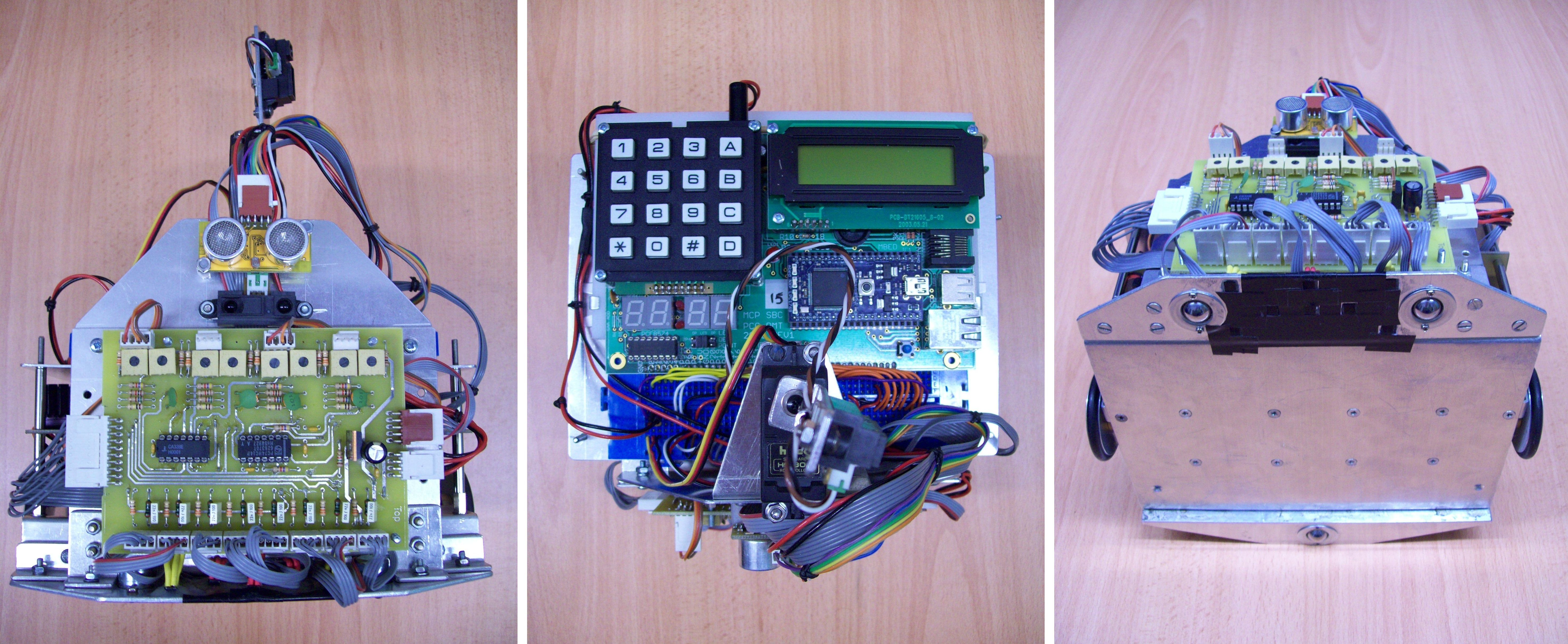
Figure 1.1 : Line follower interface PCB and sensors.
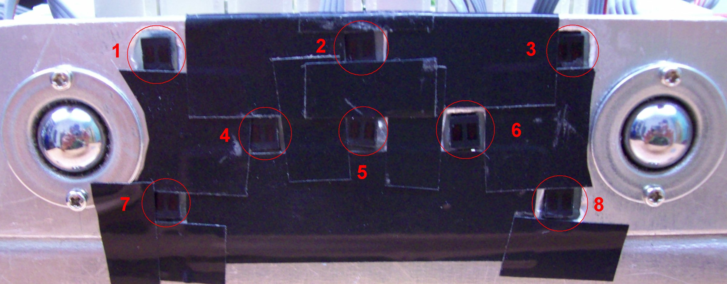
Figure 1.2 : Line follower sensors.
These eight sensors are connected to the front mounted interface board (pcb and schematic below). When in operation the robot is placed on a black surface and has to follow a white line, therefore, the intensity of the reflected light can be used to detect the line. Initially the IR diode and the IR transistor were wired to fixed resistors i.e. the intensity of the IR TX and the gain of the IR RX are fixed. This gives a Boolean output for each sensor. Ideally each sensor would be able to vary the IR TX intensity and have a variable RX threshold / gain, however, this would require quite a bit of hardware. Note, may be worth investigating the advantages of this i.e. improvements in sensor data accuracy for later versions of this robot. However, for this prototype a simple RC charge/discharge circuit was used to approximate multiple analogue to digital converter (ADC). Pulse width modulation (PWM) is used to vary the intensity of the IR TX. With a little bit of adjustment each sensor can produce an output with a 2 - 3 bit resolution i.e. 4 - 8 levels. This will hopefully allow the robot to detect the line when it is between sensors e.g. when the robot deviates from the line. In operation each sensor is connected to a digital IO port. Initially this port is setup as an output, driving a logic 1 onto the ouput line for approximately 50us, charging the associated capacitor to VCC. The port is then switched to an input, setting the line to a high impedance state. The rate at which the capacitor discharges to zero is therefore proportional to level of reflected light i.e. the current following through the IR transistor. During this discharge period the eight inputs are polled by the processor at fixed time intervals and the zero crossing times recorded i.e. time is proportional to the reflected light level.
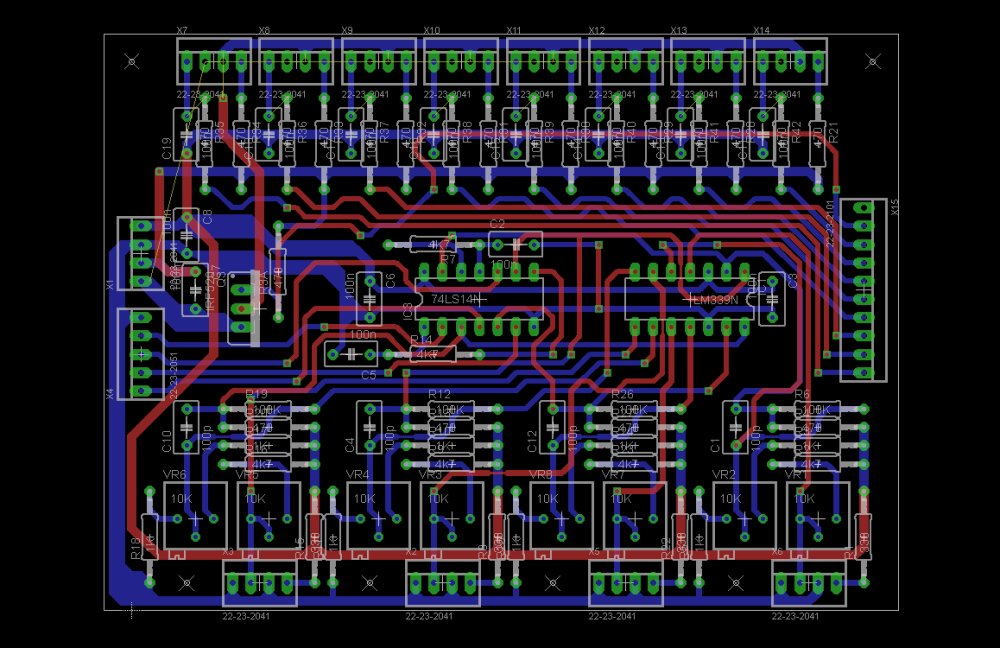
Figure 1.3 : Line follower interface board.
The average brightness of the infra red transmitters can be varied by the processor by adjusting the ratio of ON time to OFF time of the MOSFET driver i.e. pulse width modulation. Well, that's the theory, at this time when PWM is used very strange things happen to the sensors, multiple false reading are produced, again suspect software libs. Therefore, at present the IR TX are turned fully on i.e. used to turn the LEDS off to save power when not used. The final circuit on the interface board uses four analogue comparators, these are used to clean up the wheel encoder sensors. These sensors are again OPB608 modules positioned close to the wheels. Mounted on each wheel is an encoder disc, as shown in figure 1.4, depending on the acetate template used these will generate either 32, or 64 pulses per revolution i.e. IR transistor is connected to the analogue comparator, its threshold is set to detect the variation in reflected light due to the black/clear regions. Note, these signals are used to generate interrupts on the CPU, therefore, all noise / glitches must be removed i.e. requires Schmitt triggers and first order filter to prevent false counts, it may also be necessary to have additional filtering in software, minimum pulse width detection, band pass filters etc. Knowing the drive wheel circumference this data can be used to estimate the distance travelled by the robot i.e. dead reckoning. Additional software routines could also be used to increase sensor resolution e.g. edge detection / inter pulse interpolation etc.
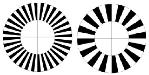
Figure 1.4 : Wheel encoders.
The motor drive circuit is based on a standard, if a little dated H-bridge, as shown in figure 1.5. This circuit (PCB) is a little on the large size, taking up the whole of the middle layer (can control up to four DC motors), however, its very robust, more than capable of handling the drive motor worst case powerdemands. Note, the motors used in the robot are highly over powered, as such if the motors were turn on, full power from a standing start, the resultant voltage drop (power drain) will reset the processor, therefore, motor speed must be changed with a linear acceleration to prevent these high current spikes. Motor direction and speed is controlled via three digital inputs. Two inputs control a motors direction: 00=freewheel, 01=clockwise, 10=anticlockwise and 11=regenerative braking. The third control line is a PWM input, controlling the speed of the motor.
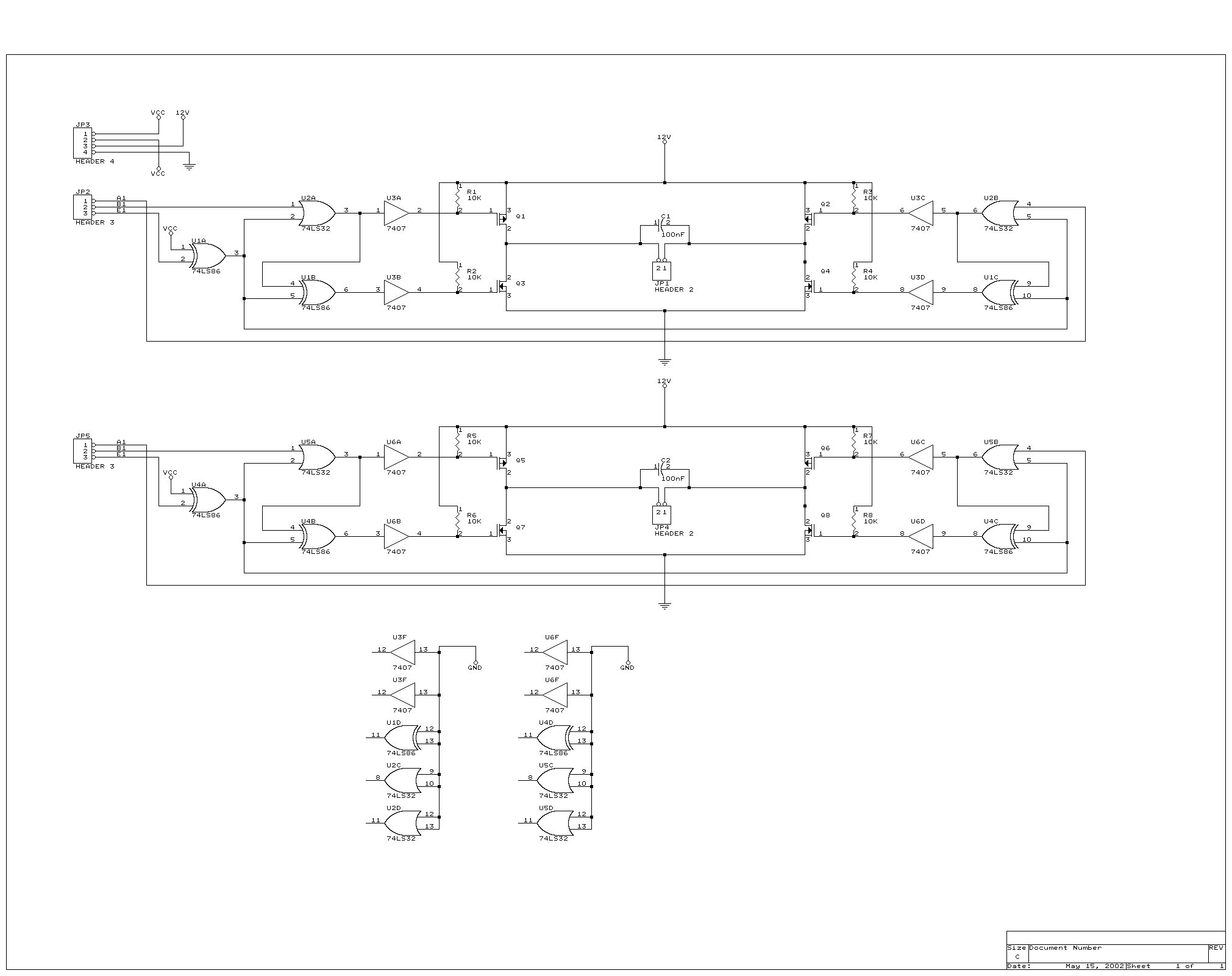
Figure 1.5 : H-bridge motor driver.
This is a simplified line follower problem. The aim of this event is to follow a straight line in the fastest time. However, moving a robot in a straight line is easier said than done. A number of difficulties must be overcome, these are generally classified as systematic and non-systematic errors. Systematic errors have a number of causes, but their main characteristic is that they are constant, producing the same 'repeatable' error e.g. the drive wheels are slightly different sizes, such that if these are turned the same number of rotations the robot will travel in a curving trajectory, rather than the desired straight line. Non-systematic errors are due to random affects which are a little more difficult to compensate for e.g. wheel spin, surface bumps / lumps / slopes etc. All of these error sources need to be taken into consideration and were possible compensated for in software. In addition to following a straight line the robot must also stop within a defined braking zone. To allow the robot to detect this floor markings and an end wall (foam pad) are used. Floor markings can be detected using the line following sensors, ultrasonic and infra-red distance sensors are used to detect the end wall. Datasheets for these two sensors are given below:
The ultrasonic module is a digital sensor, its output is read via an I2C interface. The infra-red sensor generates an analogue voltage inversely proportional to distance. This can be read using one of the processor's on-chip analogue to digital converters (ADC).
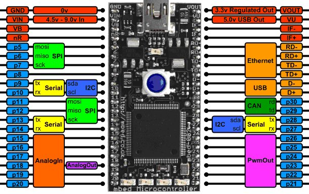
Figure 1.6 : mBed processor module.
The processor board used is the York CS mBed platform (Link), which is based around an ARM processor module. For more information on the mbed NXP LPC1768 processor module and its online software toolset go to this - Link. The microcontroller's IO pins can be configured to have a number of different functions e.g. digital IO, ADC, PWM etc. The pin configuration for this robot and a set of simple software test routines (WARNING: these are very rough and ready test routines) are given below:
A collection of useful papers and web pages Link
It is intended that this robot builds upon the research of the previous prototypes. Design, implementation and testing with be undertaken by students. Suggested work packages to be completed:

This work is licensed under a Creative Commons Attribution-NonCommercial-NoDerivatives 4.0 International License.
Contact details: email - mike.freeman@york.ac.uk, telephone - 01904 32(5473)
Back