Do you like to torment small soft toys? Then this is the web site for you :).
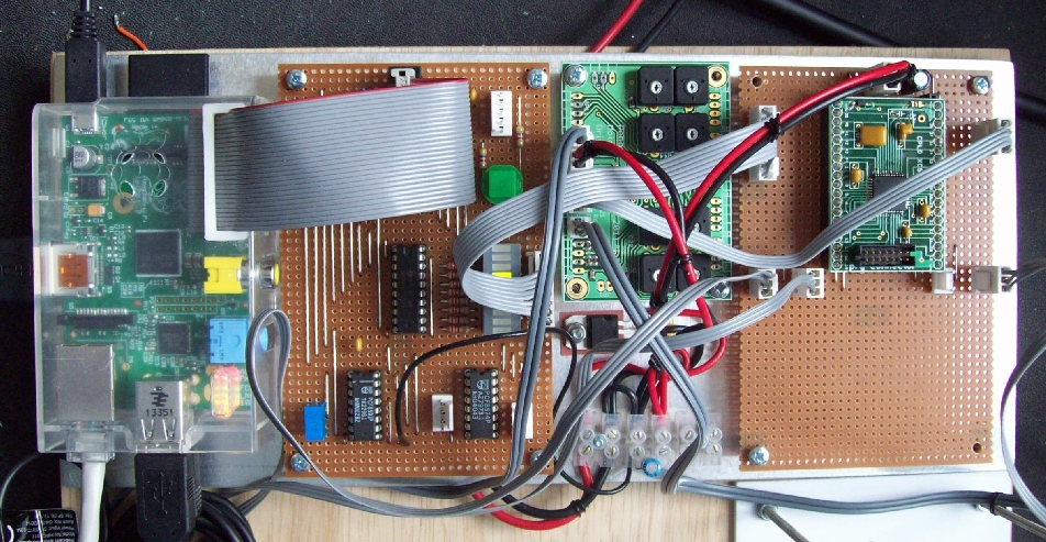
Inspired by the undergraduate open Pi competition (Link ) ( Local ) i decided to build a Raspberry Pi based project. After going through the scrap pile i found two motors, dual motor controller, CPLD (programmable hardware module) and various other bits and bobs. Combining these with a web camera i constructed the hardware below.
Figure 1.1 : Raspberry Pi + interface hardware
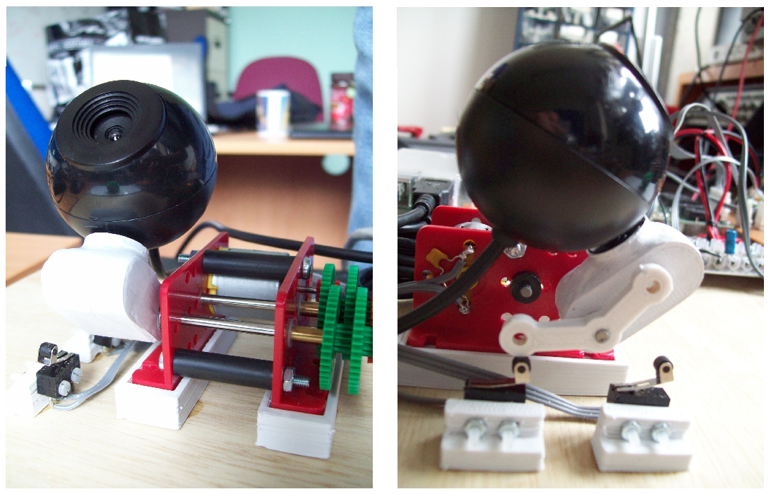
Figure 1.2 : Video stream - web-cam + motor + limit switches
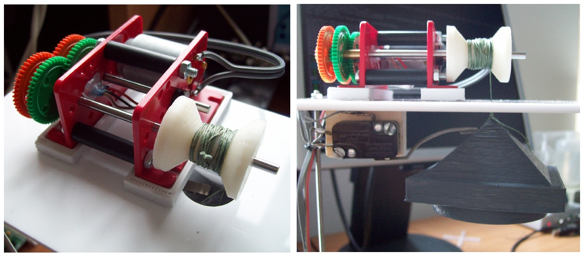
Figure 1.3 : Winch - motor + weight (grey block) + limit switch
I then needed to find a purpose for this new creation. Bob (below) is the 3D printer mascot, however he has been pressed into a different service. To make sure Bob can't run away i super-glued him to the base under the weight (figure 1.3), approximately 250g, quite enough to flatten any unsuspecting toy. His life is now in the hands of the students taking the ICAR module. Each time a question is answered incorrectly during a lecture the weight is lowered. If five questions are wrongly answered, Bob dies :(

Figure 1.4 : Bob
To monitor Bob's peril you can watch the video stream and control the web-cam's elevation by accessing the web page hosted on the Raspberry Pi (link below). However, owing to the joys of firewalls these are only accessible from a local ip address i.e. on campus
** Bug press Web Page: LINK ** (due to firewall only works for 144.32.XX.XX ip addrs)
The software used on the Raspberry Pi to control the web camera, general purpose IO, and host the web page are listed below:
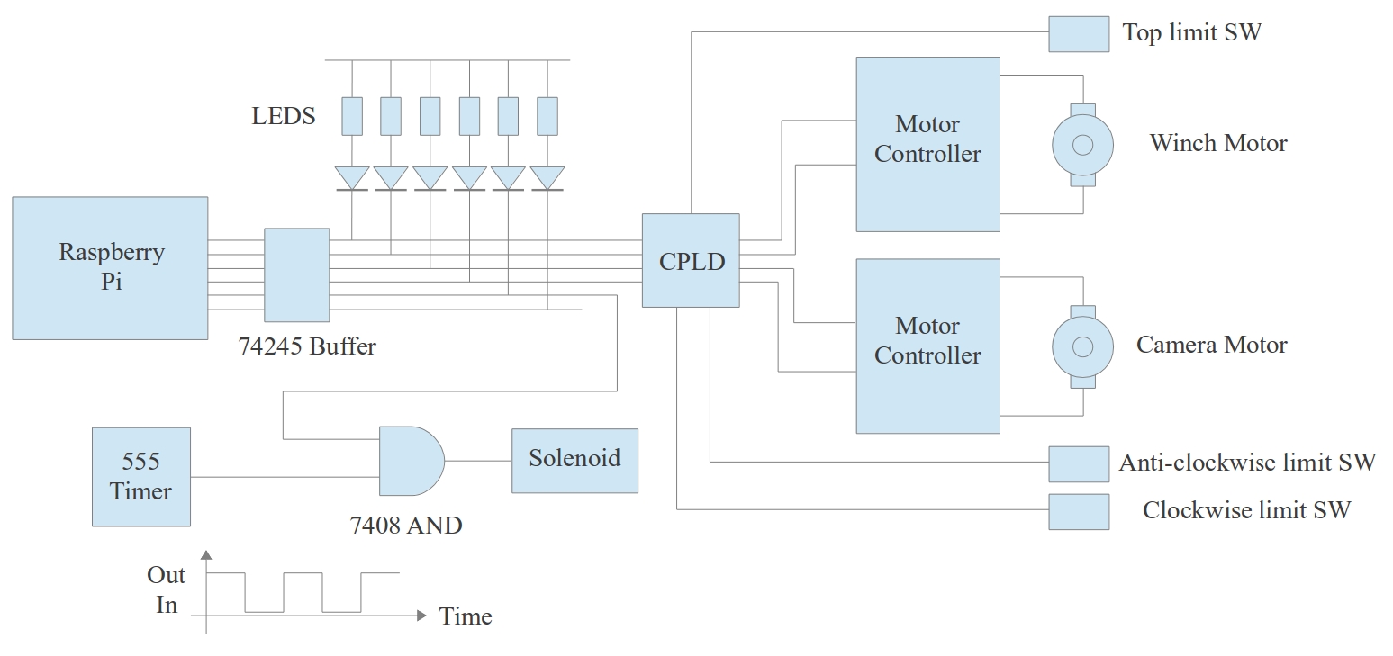
Figure 1.5 : System block digram
Apart form the fun of tormenting small soft toys this project also illustrates the design decisions taken when building any embedded system. Software provides the ability to create complex, yet flexible solutions, however, this is only one part of the final solution. Typically a system's requirements are a mixture of:
When implementing this system the Raspberry Pi provides a cheap Linux based controller. Owing to the large pool of existing software packages it is therefore very easy to develop a prototype e.g. streaming video, hosting a web page etc. The basic GPIO is quite limited, however, with a little bit of careful design this can be easily compensated for by the addition of a little extra hardware. Consider the limit switches used to detect when the camera or weight have reached their end positions. This could be implemented in software using three of the GPIO lines i.e. to read (poll) each switch's status. However, using this technique would require scarce GPIO lines and could potentially introduce delays e.g. owing to the OS, or other processes delaying the CPU from testing these signals. Such delays could damage the motors or related mechanical components e.g. not tunring the camera motor off quickly enough when it reaches its bottom limit. A simple alternative is to implement this system function directly in hardware, in this case in the CPLD programmed in VHDL (me being lazy), as shown below.
---------------------------------
-- Motor Control Logic
---------------------------------
library IEEE;
use IEEE.STD_LOGIC_1164.ALL;
entity logic is
Port (
ctl_in_1_A : in STD_LOGIC;
ctl_in_1_B : in STD_LOGIC;
sw_1_A : in STD_LOGIC;
sw_1_B : in STD_LOGIC;
ctl_in_2_A : in STD_LOGIC;
ctl_in_2_B : in STD_LOGIC;
sw_2_A : in STD_LOGIC;
sw_2_B : in STD_LOGIC;
ctl_out_1_A : out STD_LOGIC;
ctl_out_1_B : out STD_LOGIC;
ctl_out_2_A : out STD_LOGIC;
ctl_out_2_B : out STD_LOGIC);
end logic;
architecture logic_arch of logic is
begin
logic_A: process( ctl_in_1_A, ctl_in_1_B, sw_1_A, sw_1_B )
begin
if ( ctl_in_1_A ='0' AND ctl_in_1_B = '1' AND sw_1_B = '0' ) or
( ctl_in_1_A ='1' AND ctl_in_1_B = '0' AND sw_1_A = '0' )
then
ctl_out_1_A <= ctl_in_1_A;
ctl_out_1_B <= ctl_in_1_B;
else
ctl_out_1_A <= '0';
ctl_out_1_B <= '0';
end if;
end process;
logic_B: process( ctl_in_2_A, ctl_in_2_B, sw_2_A, sw_2_B )
begin
if ( ctl_in_2_A ='0' AND ctl_in_2_B = '1' AND sw_2_A = '0' ) or
( ctl_in_2_A ='1' AND ctl_in_2_B = '0' )
then
ctl_out_2_A <= ctl_in_2_A;
ctl_out_2_B <= ctl_in_2_B;
else
ctl_out_2_A <= '0';
ctl_out_2_B <= '0';
end if;
end process;
end logic_arch;
The ISE project used to program the CPLD can be downloaded here: (LINK ). VHDL is an example of a hardware description language, the above description of what the hardware should do is automatically synthesised into a .jed file that can be used to configure the CPLD to become this hardware. Each motor is controlled via two signals e.g. ctl_in_1_A and ctl_in_1_B, listed in the VHDL entity. When these signals are the same i.e. 00 or 11, the motor will stop. When they have different values i.e. 01 or 10, the motor will turn clockwise (01) or anti-clockwise (10). If the associated limit switch is not activated the input command is passed to the motor controller unaltered. If however, the limit switch is hit by the rotating arm the resulting signal causes the logic to stop the motor, generating the control signal 00. The CPLD will continue to generate this signal until the Raspberry Pi GPIO sends the stop command (00/11) or change direction (01 -> 10). As this is all done in hardware there is minimal delay, less than a micro-second. An additional advantage of implementing this functionality in hardware is that if the Pi was to crash (software error / lock up) the motors will still be protected.
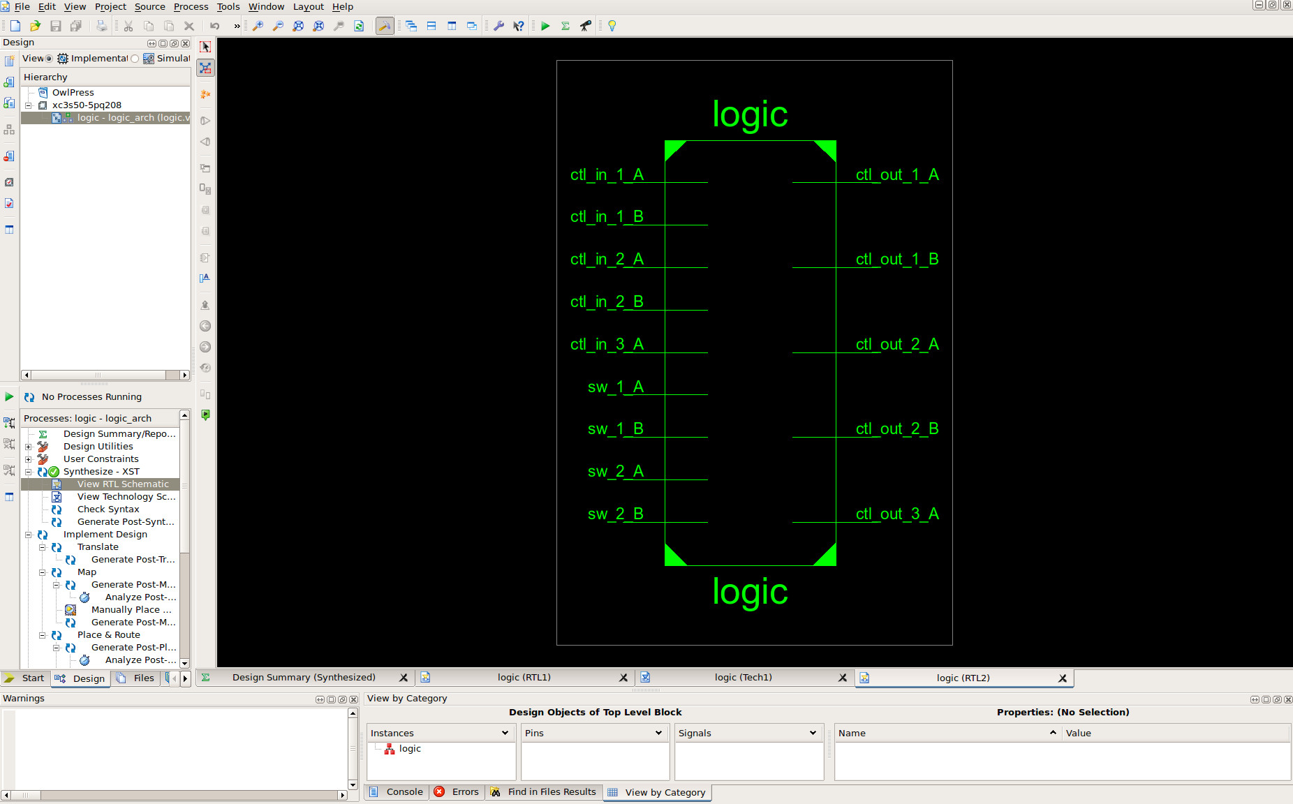
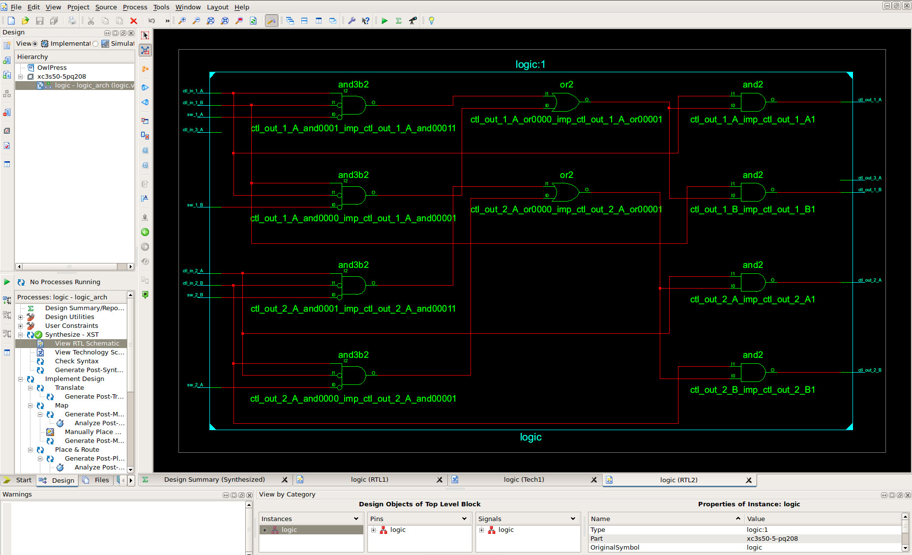
Figure 1.6 : Logic generated from VHDL

This work is licensed under a Creative Commons Attribution-NonCommercial-NoDerivatives 4.0 International License.
Back