
For those of you who don't recognise the name a Zergling is a creature from the Starcraft II universe LINK. This is a real-time science fiction strategy game in which there are three main races Terrans, Zerg and Protos. I play Terrans (humans) and I do confess normally loose to the insectoid Zerg. If you have not seen the game you may of seen the film Starship Troopers which has a similar look and feel LINK. Anyway, following my development of the robo-cockroach, it made sense to make a Zergling, as shown in figure 1.
Version 1.0 : direct drive
Version 2.0 : worm drive
Version 2.1 : motor + gearbox
Version 2.2 : prototype version
Version 2.3 : veroboard version
Version 2.4 : friction welding
Version 2.5 : PCB version
Version 3.0 : BBC Micro:Bit
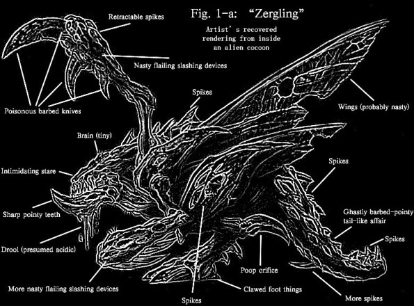
Figure 1 : Zergling (orignal sources: LINK : LINK)
As part of the Summer term week 8-10 activities i decided to put together a kit of bits so that people could make their own Zergling robot. However, one small catch, each kit was limited to £2.50. Also wanted to show how the electronic building blocks taught in FESC could be applied to this real world application. As discussed in FESC exercise 4 this means BEAM, or more precisely a phototrope
Biology, Electronics, Aesthetics and Mechanics robots, or BEAM for short, is a family of robotics that are based on simple analogue circuits. Typically BEAM robots use a set of analogue circuits to mimic biological neurons, normally nervous (Nv) neurons: LINK, allowing the robot to response to its environment. The key design approaches taken in developing these robots are:
In BEAM robotics there are a number of different classifications:
https://en.wikipedia.org/wiki/BEAM_roboticsA phototrope is a robot classification that reacts to light sources i.e. a "light turning" robot. This class can be subdivided into photophiles (seek light) or photophobes (flee from light). These classes linked into the Starcraft back story, as some types of Zerglings don't like light.
With these aims in mind, i started making the 3D models for the chassis, as shown in figure 2. The openscad model file is available here: LINK.
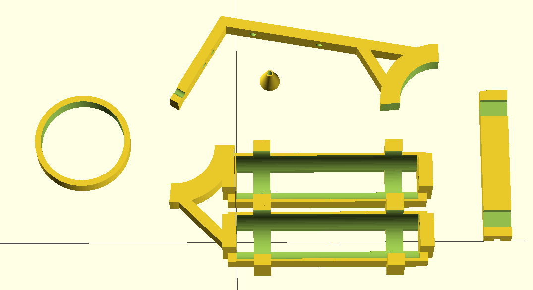


Figure 2 : 3D models, left side (top), right side (middle), head / tail (bottom)
Originally i wanted a walking robot i.e. a robot with legs, but this would require a significant torque i.e. motor with a gearbox, which are at least ten times the cost of the small D.C. motors used (30p compared with £3+). Also legged robots can be quite mechanically complex, the 3D printer already took 2-3 hours to print the components in figure 2, increased complexity equals increased printing time. Therefore, compromise 1: wheels. When assembled with the power of Kragle (super glue) it looked like this (battery boxes are supposed to be the wings):
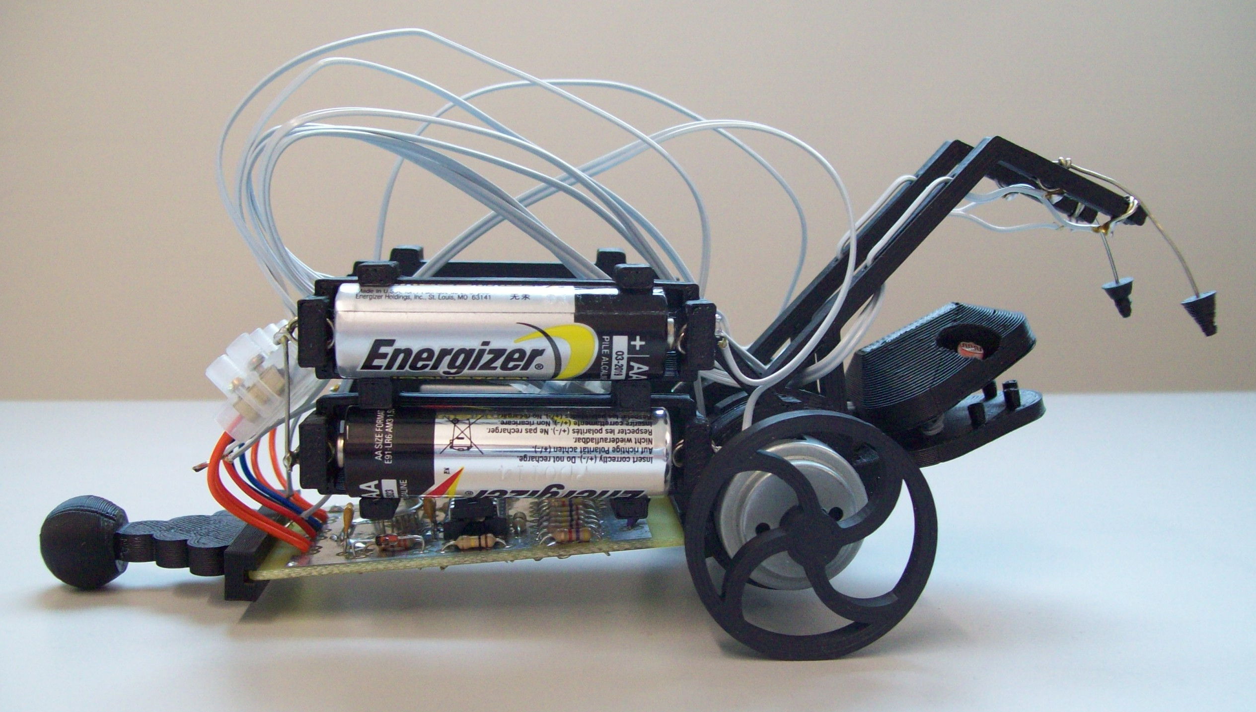
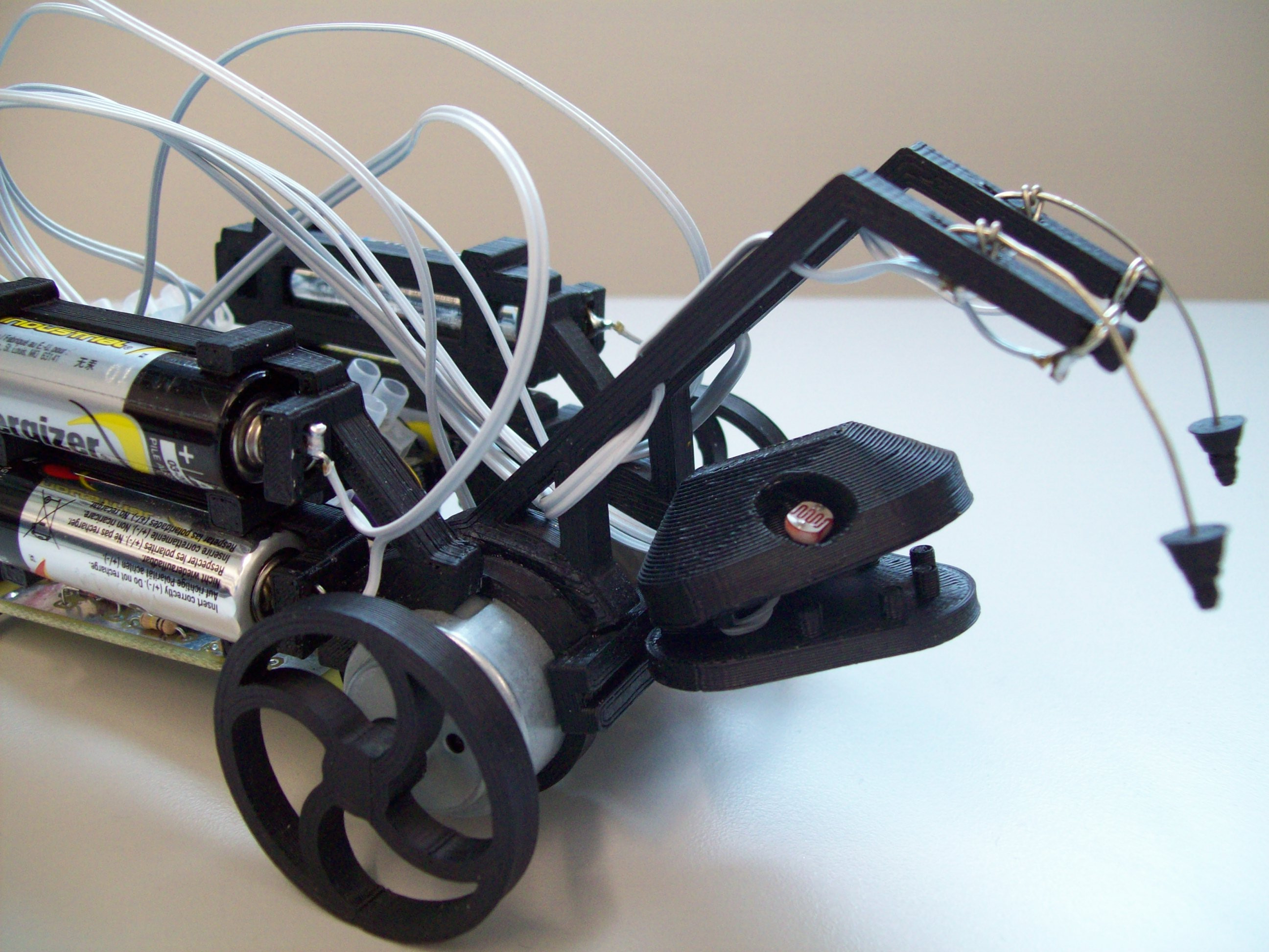
Figure 3 : Version 1.0
The robot's red 'eyes' are two light dependent resistors (LDR1 and LDR2). If the light levels falling onto both of these sensors is the same, the robot will go forwards. If the light levels differ, the robot should move away from the light. To control the two drive motors the block diagram shown in figure 4 was constructed. The two drive motors are wired in series across the +3V and -3V supply rails. In theory if the motors are the same they will turn at the same speed, moving the robot forwards in a straight line. To make the robot turn the speed of one motor needs to be reduce and the other increased. This can be achieved by increasing or decreasing the voltage at the junction of these two motors i.e. VOUT. The primary behaviour of this robot is to move away from the brightest light source within its field of view:
When light falling on LDR1 and LDR2 is the same intensity the output of the subtractor will be zero, so the robot should move forwards. However, getting a robot to move in a straight line is quite tricky e.g. if one of the drive motors is faster than the other (better magnets, less friction etc), or if the motors are misaligned, or one wheel is larger than the other etc. Therefore, the constant VOFFSET input signal can be adjusted such that the robot does move in a straight line. In addition to following lights the robot also needs to avoid obstacles. This can be achieved by the third input VTURN e.g. if the robot had a sensor mounted at the front that produces a voltage inversely proportional to distance this could be used to turn the robot into open space.
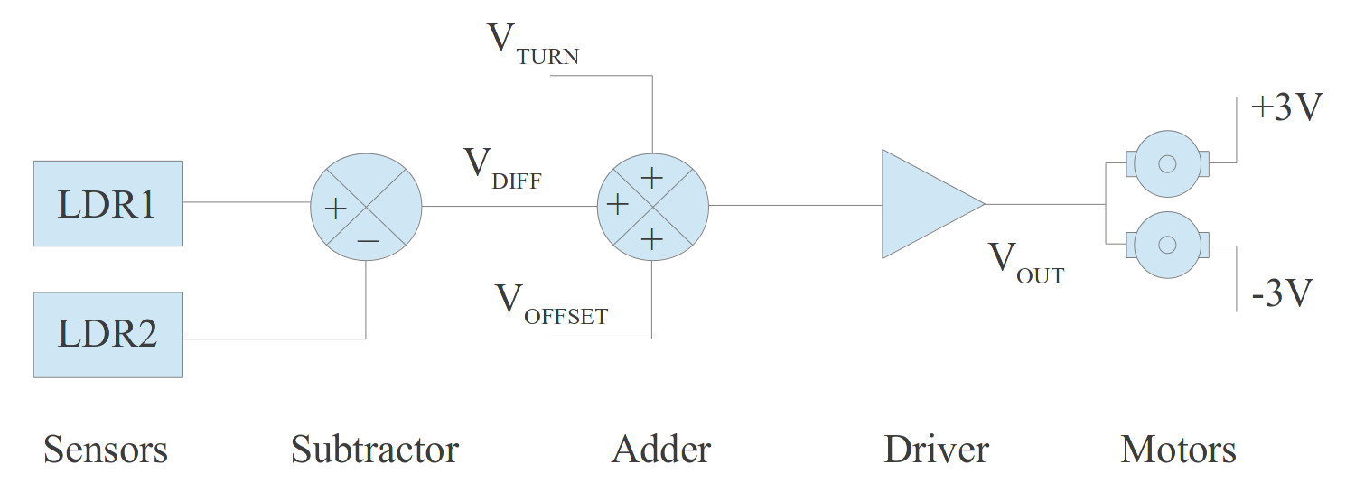
Figure 4 : Block diagram
One possible implementation of this block diagram is shown in figure 5 (click to enlarge). The eagle SCH and BRD files are available here: LINK, LINK. The two LDRs are connected to terminals X1 and X2, forming two potential dividers. Their output voltages are passed to a difference amplifier. If the light levels are the same the output (difference) will be '0V', therefore, the motors will run at the 'same' speed. If one sensor has more light shining on it, its output voltage will be smaller than the other potential divider. Therefore, depending which input of the difference amplifier is larger, the output voltage will be either a +V or -V, indicating which direction the robot should turn. The magnitude indicating the angle of turn. This output signal is then passed to a summing amplifier which adds together the VDIFFERENCE, VOFFSET (variable resistor) and VTURN (mono-stable) signals. The output of this operational amplifier can not source/sink enough current to drive the two motors directly, therefore, the signal is passed through a push-pull output driver LINK. The two motors are connected to terminals X4 and X6.
VOFFSET is produce by a variable resistor (pot) i.e. simple potential divider. Note, the resistance of this variable resistor has to be significantly smaller than the resistors used by the operational amplifier as to not affect its operation i.e. so that it looks like a voltage source. Initial VOFFSET is set to 0V, but is then adjusted such that the robot travels in a straight line.
VTURN is produced by a mono-stable. The original aim was to use a distance sensor, however, this would of exceeded the £2.50 limit. Therefore, a less elegant solution was used. When the robot hits an obstacle one of the two simple switches mounted on the robot's front arms will trigger a mono-stable timer, generating a pulse. This signal will cause one of the motors to turn on fully, hopefully power sliding the robot away from the obstacle (well that was the hope). This mono-stable is made from a simple RC circuit combined with a comparator. When the switches on the arms are triggered, the capacitor is discharged to 0V (both switches are connected to terminal X3). The operational amplifier's output (comparator) will switch to VMAX, causing VOUT to also go to this voltage. Note, should change the gain of this input to ensure this. With the output driver set to VMAX the 'top' motor will stop and the bottom motor will have double the voltage, therefore, run at 'twice the speed. Although this circuit works the lack of grip from the wheels and the weight of the batteries prevented the robot from spinning (turning). The PCB of this circuit is shown in figure 6. Pete then minimised my layout to the final version shown in figure 7.
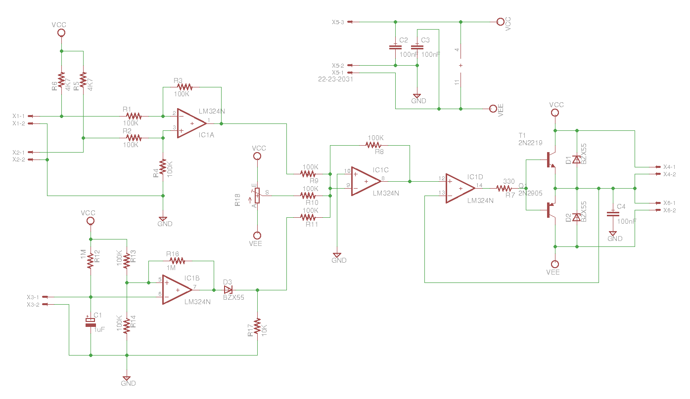
Figure 5 : Schematic V1.0

Figure 6 : PCB V1.0
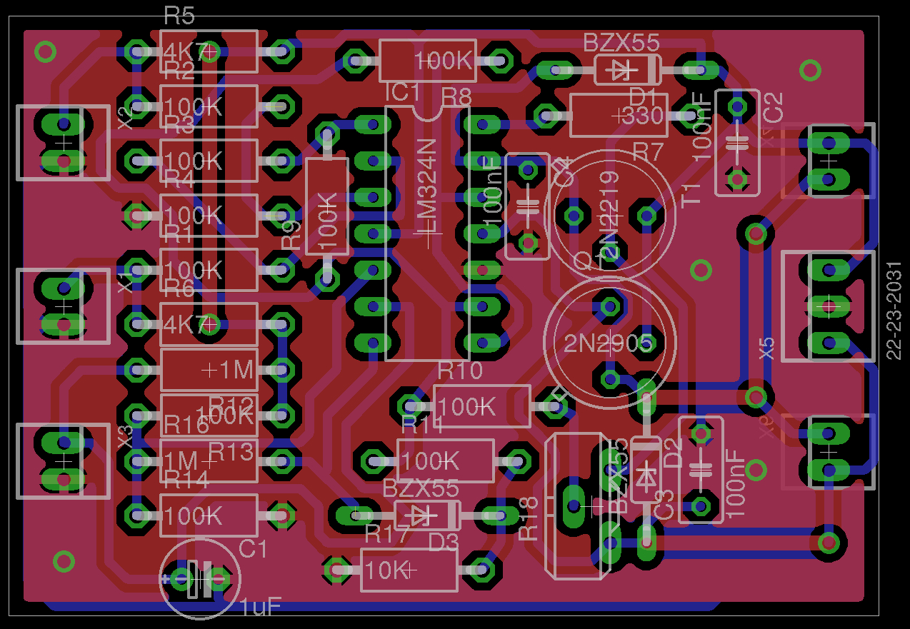
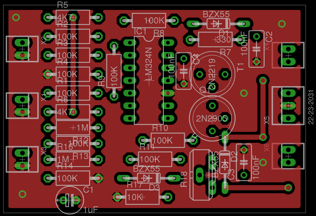
Figure 7 : PCB V1.1: layers - Bottom - Top.
Version 1 sort of works, the speed of the motor varies quite nicely with different light level e.g. the robot will follow a torch. Obstacle avoidance however, doesn't work. Also had problems with contact pressure in the battery boxes. Too light and you have an open circuit, too much and the plastic snaps.
To improve the robots movement i decided to add a gearbox. The robot did follow the light, but it was a little quick, slowing down the motors will allow the robot to track the light source more accurately, stop overshoots. Worm drives are normally one of the most compact gearboxes, to simplify construction decided to used the drive cog as a wheel, as shown in figure 8. The openscad model file is available here: LINK. To improve motor control, especially object avoidance, redesigned the operational amplifier circuit. Again, used a mono-stable triggered by bumper switches, but this time the circuit will reverse one of the drive motors to ensure the robot will spin around. The updated circuit diagram is shown in figure 9. The eagle SCH and BRD files are available here: LINK, LINK.

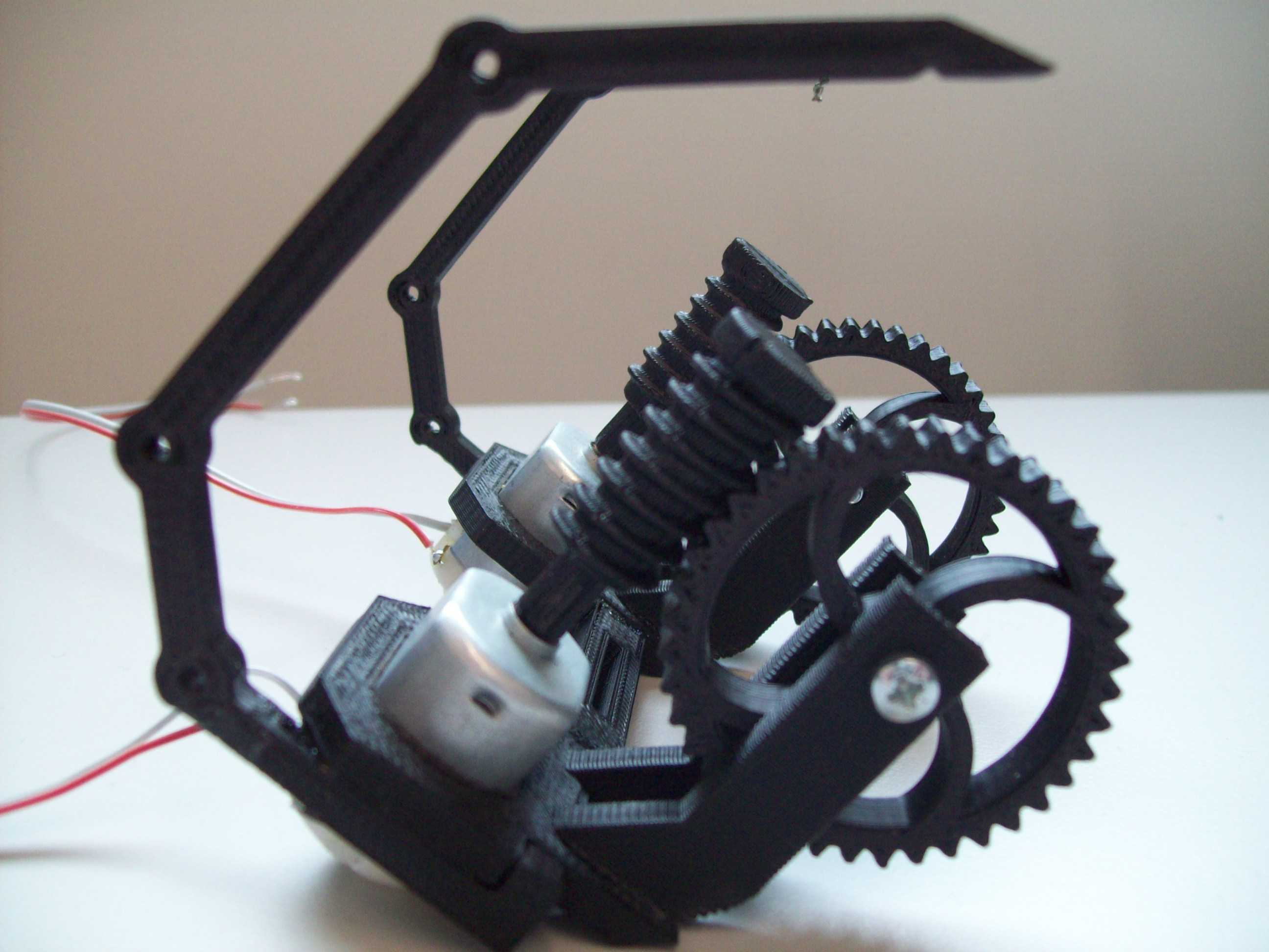
Figure 8 : Version 2.0 - 3D model (top), gearbox (bottom)

Figure 9 : Schematic V2.0
This circuit is the Zergling's brain and can be considered to be a simple artificial neural network (ANN). I do confess i don't know a lot about neural networks, so the description below is based on my limited understanding i.e. there may be errors :). As we all know ours brains are made of neurons, the body of the neuron is the Soma, which has Dendrites (inputs) and an Axon (output), as shown in figure 10. We can approximate the behaviour of these neurons with the following equation:
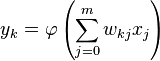
where there are m+1 inputs (x0 to xm), each with a weighting (w0 to wm). The output y of this neuron, the kth neuron in the network, is the transfer function φ (phi) of the sum of these weighted input terms. This 'activation' function can take a number of different forms, normally a Sigmoid function LINK. However, for this hardware neural network we are using simple Linear and Step functions (a lot easier to build).

Figure 10 : Neuron
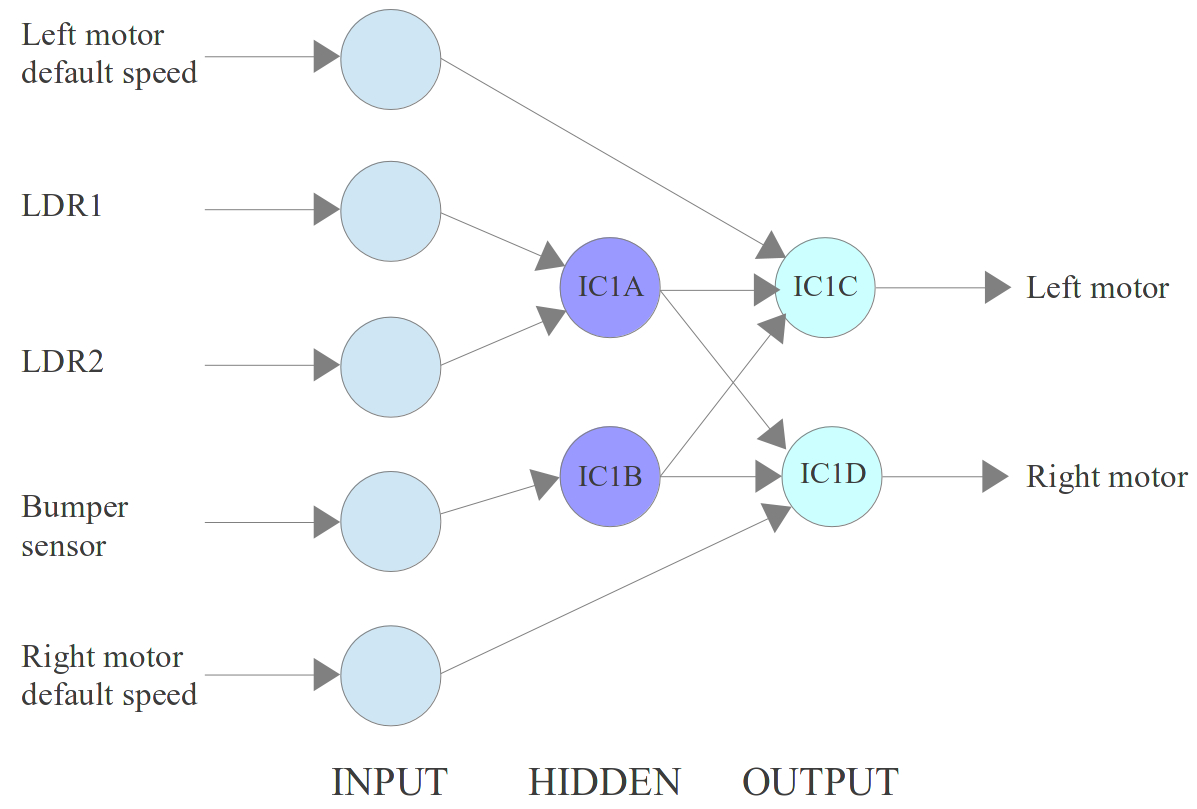
Figure 11 : simple neural network
The neural network block diagram for the circuit shown in figure 9 is shown in figure 11, circles are neurons, arrows are synapses. A neural network normally has three layers: input, hidden and output. The input layer is normally passive, simply distributing the input signals to one or more neurons. The hidden and output layers then process these signals using the equation previously defined. This network has three inputs (LDR1, LDR2, BUMP) and two outputs (LEFT_MOTOR, RIGHT_MOTOR). It also has two constant that determines each motor's default speed. In the circuit each neuron is made from an operational amplifier. As there are only four operational amplifiers in the 14 pin package (IC1A - IC1D), so our Zerglings can only have four Neurons. For comparison:
A more detailed view of this neural network is shown in figure 12. VCAP is the voltage across the capacitor discharged by the bumper switches. VREF is the potential divider circuit used by the comparator. VLM and VRM are the reference voltages from the two variable resistors, defining the default level (speed) of the left motor (LM) and right motor (RM) comtrol signals. Typically this is 0.8V to 1V. Note, when mounted the two drive motors will be physically mirrored about the centre line of the robot i.e. to move the robot forwards one motor will need to be driven by a positive voltage and the other by a negative voltage. If both motors were driven by the same voltage the robot would spin in a cycle (drive voltages need to be opposite voltages such that the result of V_LDR1-V_LDR2 will speed up one motor and slow down the other).
Like all neural networks optimisation is through the adjustment of each neuron's input weights i.e. the gains of the operational amplifiers. The most effective weights to adjust are those associated with IC1A i.e. the difference amplifier. By increasing these gains the robot will become more responsive to small changes in light level i.e. it will produce larger changes in drive voltages. However, this could also lead to overshoot (turning to far) or oscillations (repeatedly turning left/right, rather than moving forwards). Initially these gains were set to 1. Another gain that can be adjusted are those associated with IC1B i.e. the mono-stable. This signal needs to set both motor drive signals to VMAX, therefore the gains associated with these inputs have to be selected to cancel out any negative inputs, such that the robot will rotate about its centre (axle). Input voltage sums larger than VMAX will saturate to VMAX i.e. the output of the operational amplifier can not be larger than the supply voltage. Talking to Simon a key element of a neuron is its non-linear input/output transfer function. To be honest i think this is were the comparison of the circuit in figure 9 to a neural network falls down a little. To follow (or runaway) from a light source i do want that linear relationship between changes in light level across the LDRs and changes in motor speeds e.g. small difference in light = small change in motor speeds etc. The non-linearity in the circuit at present is saturation, this being determined by the summing/difference amplifier gains, as shown in figure 12. Higher gain will produce sharper/faster rates of turn, but i'm not sure this will make a better light follower. If i get time will replace some of the fixed resistors with variable and see what happens.
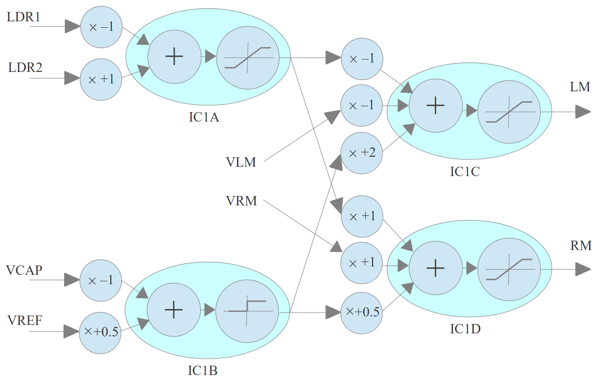
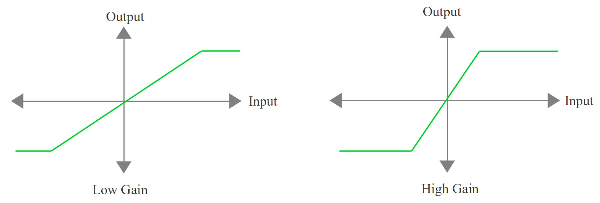
Figure 12 : expanded neural network (top), neuron gains (bottom)
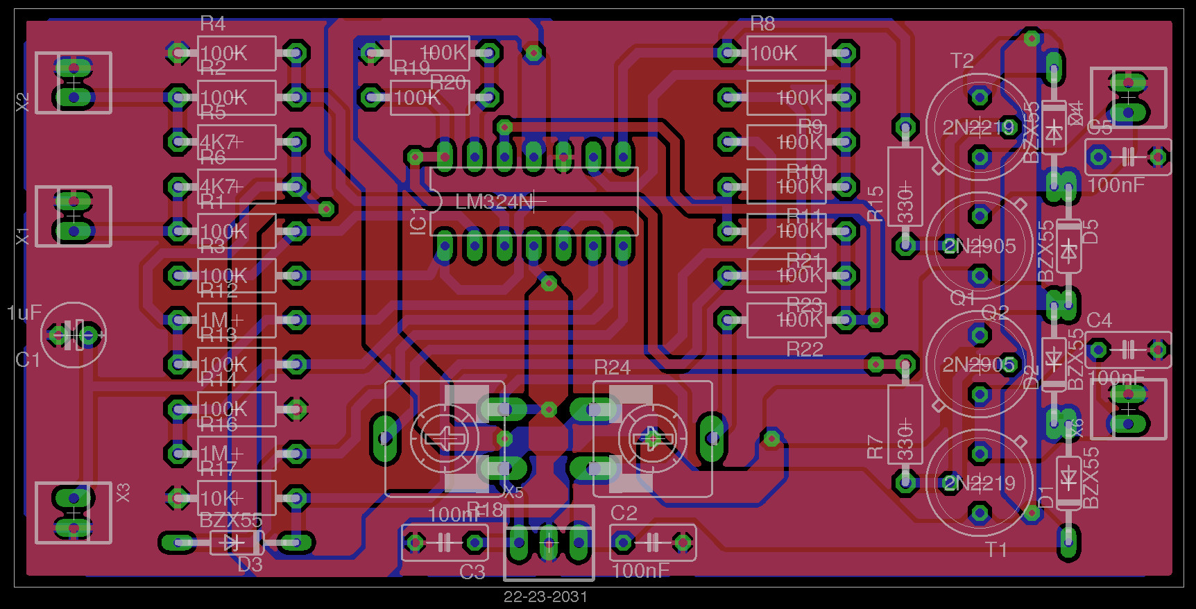
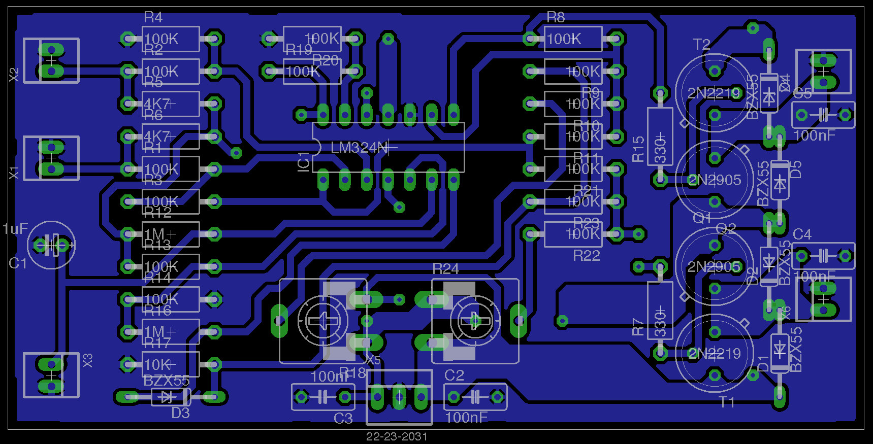
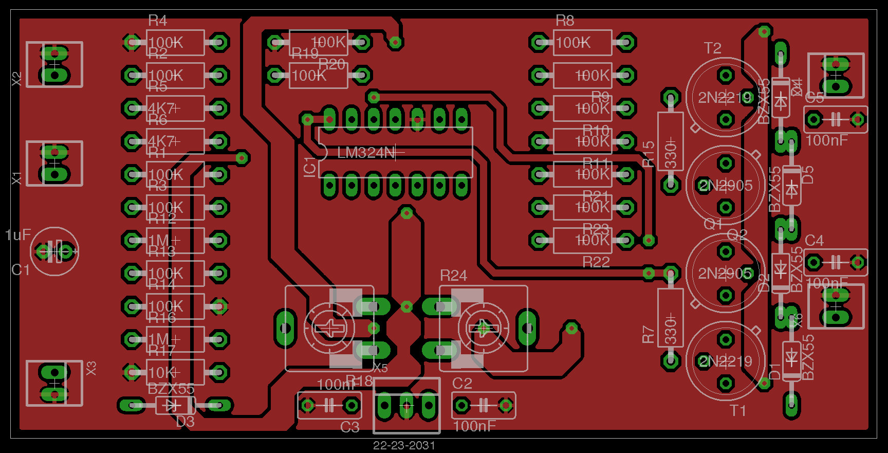
Figure 13 : PCB V2.0: layers - Bottom - Top.
The final pcb is shown in figure 13. There are a couple of differences in the circuit shown in figure 9 and the neural network in figure 12, mostly notably the gains. For initial testing all gains were set to 1. These will be adjusted, 'trained' during testing to achieve the desired behaviours.
Parts List (RAPID)
Components = £2.54
PCB = £0.89
Plastic = £0.80
Total = £4.23
A little over the £2.50 budget :(, but in the right ball park. Perhaps a little more realistic cost would be £5.00 per robot i.e. the classic estimate a cost, then double it.
Made a couple of mistakes :(. The LDR signals are subtracted using a difference amplifier i.e. 0V robot move forwards, +V robot turn left and -V robot turn right. Therefore the two reference voltages produced by the variable resistors need to be opposite values e.g. +1.5V and -1.5V, such that when the difference amplifier signal increases or decreases, one motor will speed up and the other will slow down, turning the robot towards the light. Therefore the summing amplifiers will need to be the same i.e. inverting or non-inverting, not different types. During testing it was found that there was quite a large difference in the motors i.e. for the same voltage motor speed does vary quite a bit. This impacts the obstacle turning signal, as it needs to be substantively larger than the light or reference voltages to ensure that the robot does reverse one of its motors e.g. if one motor need -2.5V to move forwards i will need a +5V voltage swing to reverse that motor. Therefore, a simple solution is to move to +9V batteries i.e. +9V / -9V supplies, this ensures that both operational amplifiers saturate with opposite values. The final problem is the worm drive. Because the worm cog had to be printed in two halves the layers produced during the printing process cause the gears to bind on the drive cog / wheel. One solution would be to smooth the worm i.e. sand / file, but this would be tricky and take a long time. Therefore, will need to buy cast gears or a cheap gearbox. However, on a positive note, apart from one wheel going backwards (due to the wrong summing amp) the circuit works fine. This bug is easily fixed by changing one of the amplifiers, as shown in figure 14
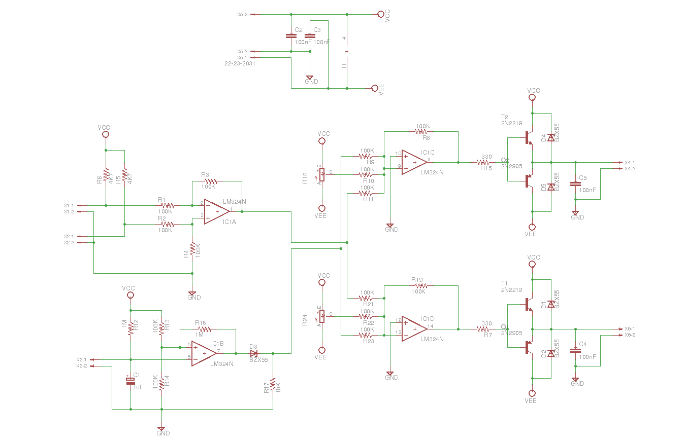
Figure 14 : Schematic V2.1
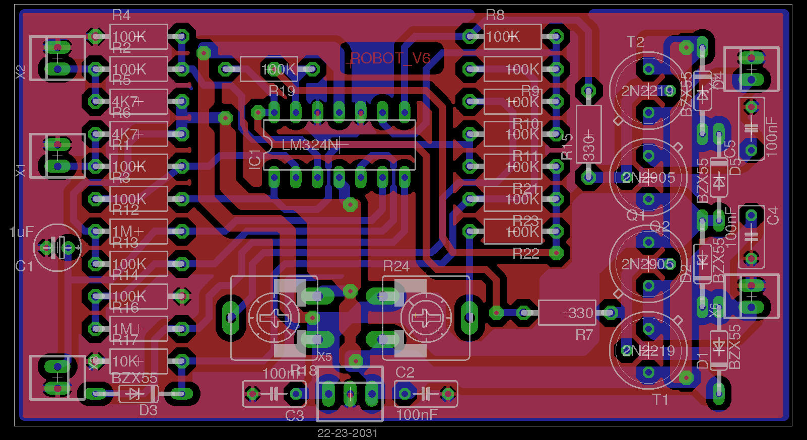
Figure 15 : PCB V2.2
More joy, nobody sells the 2NXXXX transistors, had to move to a different type BD135 LINK and BD136 LINK, as shown in figure 18. These have a different footprint, therefore i had to redesign the PCB layout again :(. However, on the plus side these transistors can handle larger currents and make the board a little smaller. Found a cheap gearbox for the existing motors, 200:1 reduction, as shown in figure 16, only £1.21 the pair. Hopefully the final PCB layout is shown in figure 17. The eagle SCH and BRD files are available here: LINK, LINK.

Figure 16 : motor + gearbox
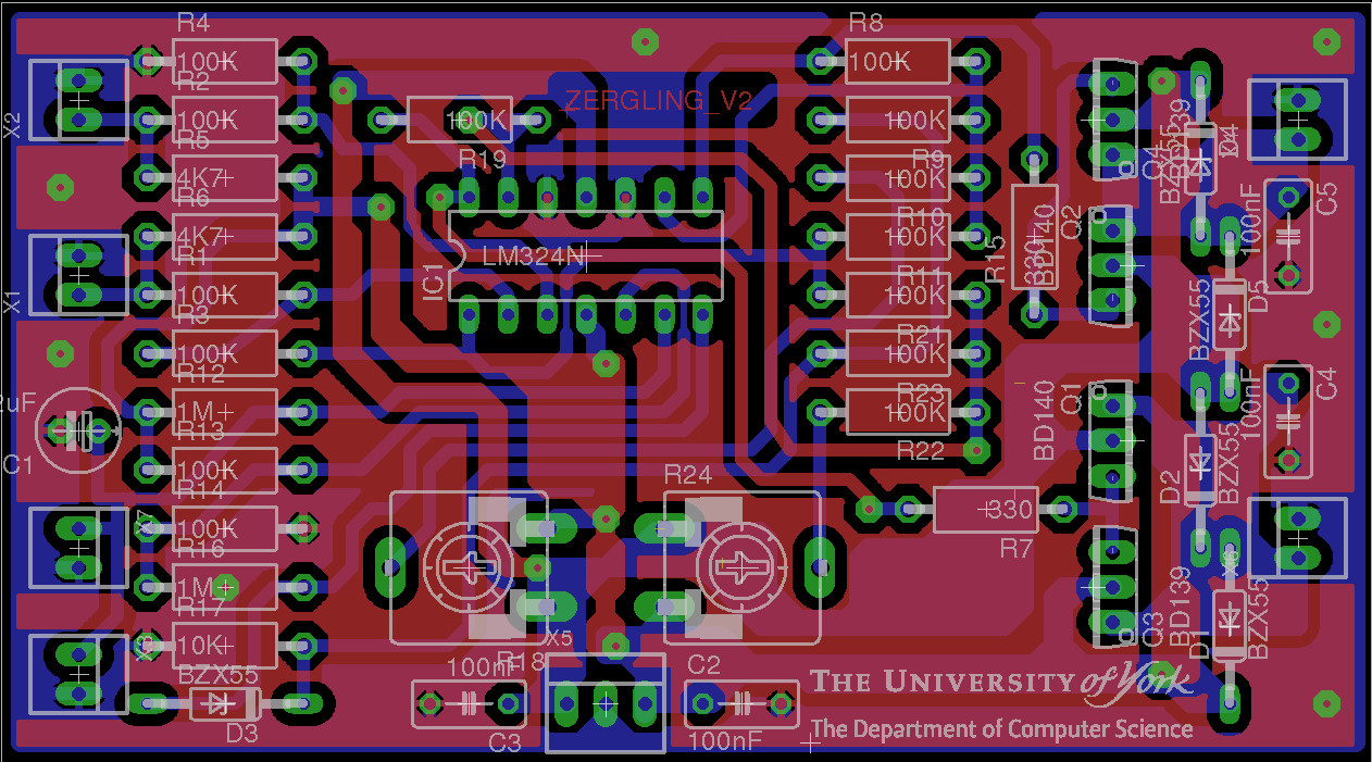
Figure 17 : PCB V2.3
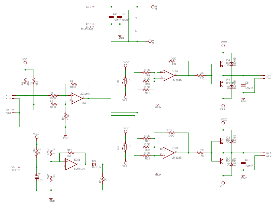
Figure 18 : Schematic V2.2
The move to 9V batteries simplifies the 3D printing a lot, single print run, taking approx 2 hours, as shown in figure 19. The main plus is no battery boxes, which to be honest were a little tricky to build (contact pressures). To test this new board decapitated the first zergling, a noble death (new version has a slightly smaller head). The new and improved chassis is shown in figure 20. The openscad model file is available here: LINK. Here is a video clip of the robot in action, its tethered via a power cable, but it does show all of the main functions: LINK, LINK, LINK (had troubles with some browsers, video/sound ok when downloaded).
Testing showed that the variable resistors allow good speed adjustment, from the very slow to full ahead. One unanticipated affect is that if the default speeds are relatively slow, then a large change in light levels will actually cause one of the motors to reverse i.e. allowing the robot to turn on the spot, rotating the chassis towards the light source. Battery currents look reasonable, each motor taking current form a separate +9V battery, ensuring that both batteries are discharged relatively evenly. One problem still to fix is that the voltage that defines each motor's default speed will change as the batteries are discharge, really need a regulated reference voltage, but that will increase costs / complexity.

Figure 19 : Version 2.1 - 3D printing
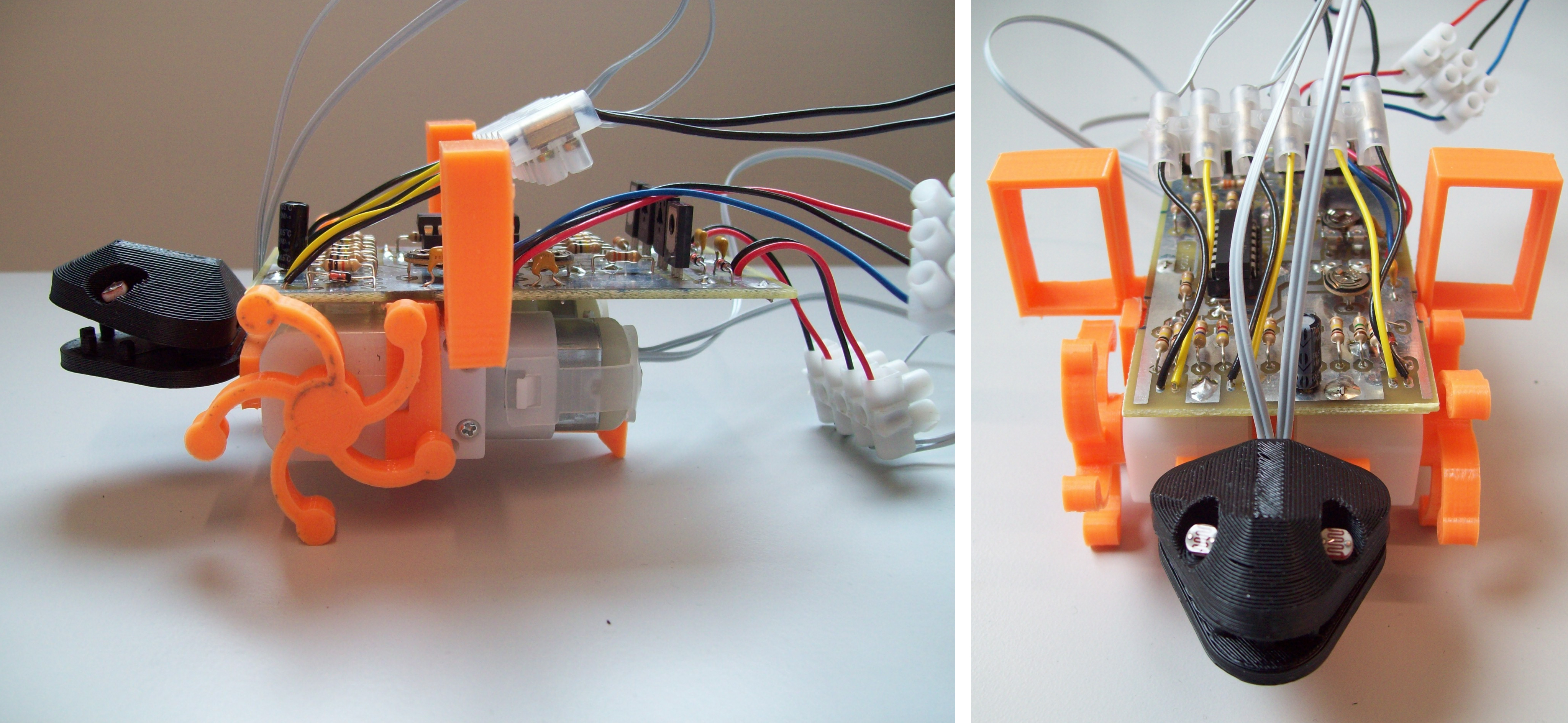
Figure 20 : Version 2.1 - chassis
Strictly speaking zerglings should really be a purple colour, but gone with a orange and white colour scheme (that's the plastic on the printer at present). The final beasty is shown in figure 21. The 3D printed pieces will need a bit of finishing i.e. sanding / filing to remove waste plastic, flash. The three main body part should click together, there may be a little warping, so small 'adjustments' may be needed, but ideally they should be flush. A little super glue normally finishes the job. Note, after years of Warhammer i have learnt what super glue can and can not do, two words of wisdom: LESS IS MORE and ALLOW IT TO DRY, don't try to flood fill as the glue will just run off, or it will take a day to dry. Blowing and water can help set the glue, but never quite as strong as just waiting. Motors should just slide into the 'body', again you may need to remove any waste plastic along the bottom edge to allow it to fit. Note, the white locating post on the motor should slide into the notch. Solder on two wires, note the colour coding of the wires i.e. orange on the top terminal of the motor, this will be important during final assembly. Then 5-10mm away from the solder joints twist the wires together a couple of times. Note, do twist the wires, do not wrap one wire around the other, we are looking to lock the to wires together to reduce stress on the solder joints.
UPDATE: forget gluing, friction welding is the future, also a lot less messy and easy to do (LINK). Alternatively you can also 'weld' using an old soldering iron tip (LINK). IMPORTANT: don't use a new soldering iron tip as this will just make useless for soldering. A video of the assembly and welding of the main body elements is shown in section 2.4 (further down).
Bump switches are made from single core wires (insulation removed). Glue the zerglings 'hand' (L-ish shaped pieces) on to its 'arms'. When dry (don't rush, allow the glue to fully set), push the wire through the holes, then wrap it around the plastic 4-5 times, these form the switches two contact. There is just enough 'spring' in the copper wire to hold the contacts apart, but they may need regular adjustment. Finally solder on connecting wires, be careful not to melt the plastic. Note, don't make the wire 'fingers' too long, there needs to be approx 10mm ground clearance to allow the switches to close, finally super glue the wires to the inside of the 'arms'.
The wheels are a press fit onto the drive shaft, you may have to round the top edge of the hole a little to allow the shaft to fit. Note, the wheel 'legs' should be facing forwards. The rear 'foot' is just a simple skid, unfortunately the hole that this slots into can get clogged with plastic as its the first layer printed. Therefore, you may need to use a craft knife to open up the hole a little.
The eyes are two LDRs, cut the legs to approx 5mm. Then solder on two wires, these can be either way round (its just a resistor). Then 5-10mm away from the solder joints twist the wires together a couple of times. Note, do twist the wires, do not wrap one wire around the other, we are looking to lock the to wires together to reduce stress on the solder joints. Then pass the wires through the eye sockets and bend into place. Once you have a rough idea of how the wires should be bent, remove and bend with pliers ensuring that the two soldered wires do not touch when they are feed back through. Note, you can lacquer the solder joint with a little super glue, may give it a little insulation. Finally glue the wires into the channel, making sure they are fully recessed, otherwise the top of the head will not glue onto the bottom jaw.
If you would like to make a zergling be warned its does take a while to make:
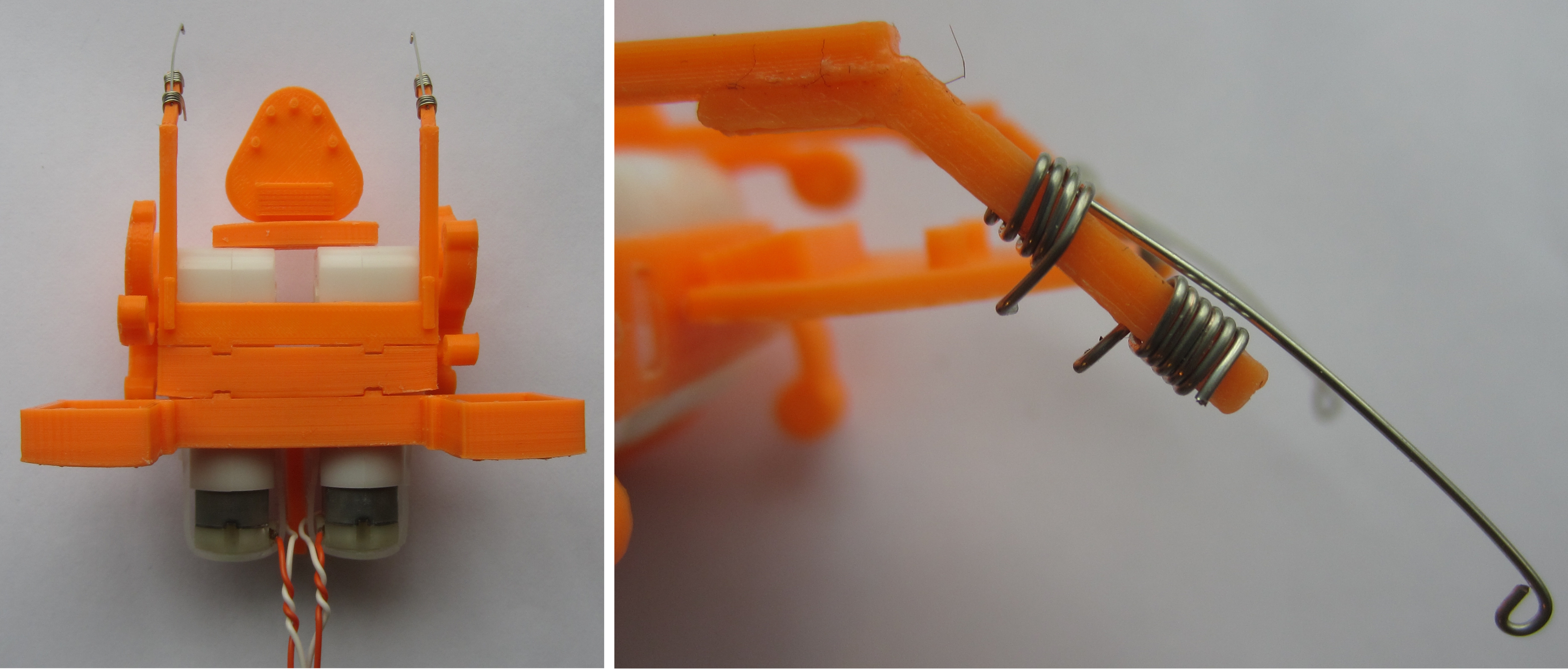

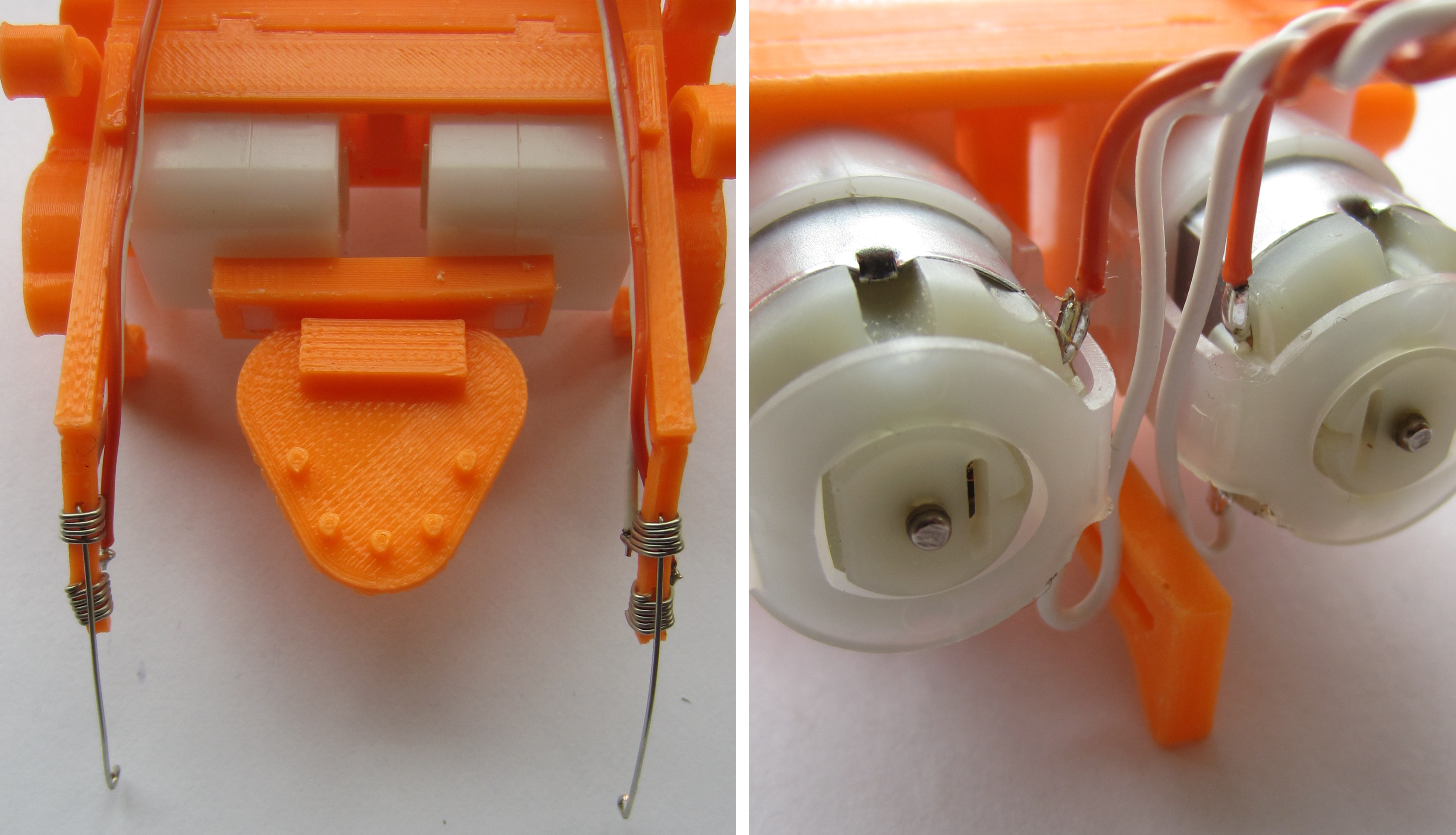
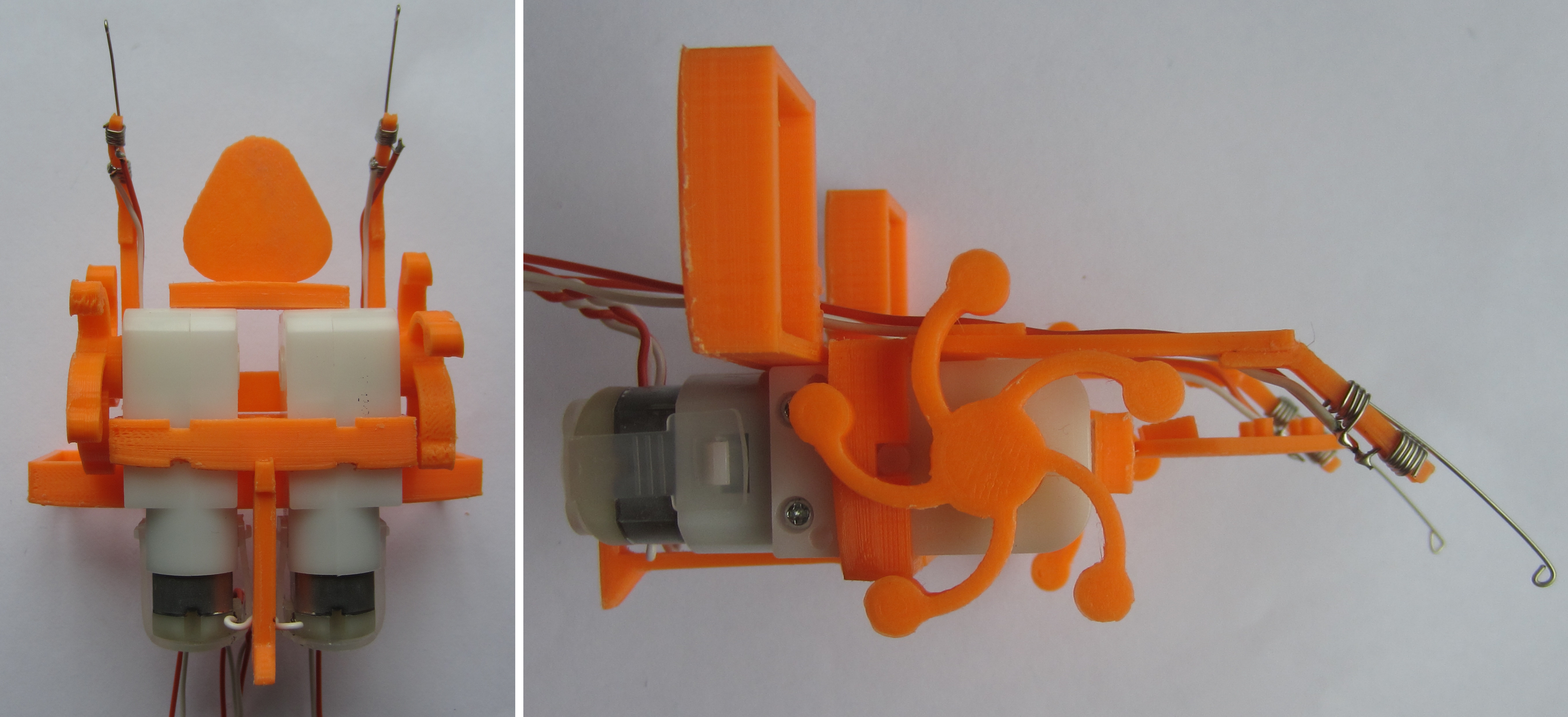
Figure 21 : Version 2.1 - final version
On reflection moving to a smaller head does looks better, but it may reduce the light following abilities of the robot i.e. the LDRs were further apart, now light falling on the LDRs may not differ significantly. To overcome this potential problem i could increase the difference amp's gains, or recess the LDRs deeper into the head. However, i think a crest will be a better solution and it will look Zergy, as shown in figure 22. Now light coming from one side is blocked by the crest, creating a shadow.
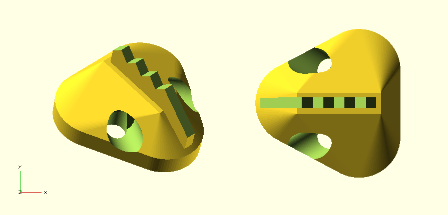
Figure 22 : Crest
Been struggling with my eyesight for a while, i tend to use the force more than my eyes when i solder now. This also stops me reading component values, as shown in figure 23 :). Be WARNED if you mix up your BD135 and BD136 they could explode.
Figure 23 : Opps, a small hole (left), should of gone to the opticians
One last mistake, however i did consider this right from the start, but decided to take a chance. Unfortunately the weight of the batteries causes the robot to wheelspin i.e. the wheels do not have enough friction to drive the robot forwards. Therefore, one final change to the 3D printing as shown in figure 24. Batteries are now mounted directly over the drive wheels. The openscad model file is available here: LINK.
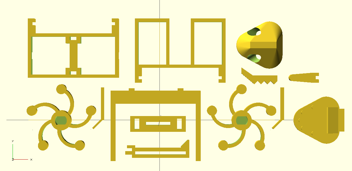
Figure 24 : Final version
If your lucky you will get an externally made board (green board) so you can skip the next two steps. The PCB (below) is made in house, shown in figure 25. Step 1: check for shorts and breaks. Using a magnifying glass make sure there are no little pieces of copper left over from the etching process e.g. between tracks etc, these will need to be scrapped/cut off. Also check that there are no cracks/breaks in any of the tracks, use a continuity tester if your not sure. If you find a break you will need to solder a thin wire on top.
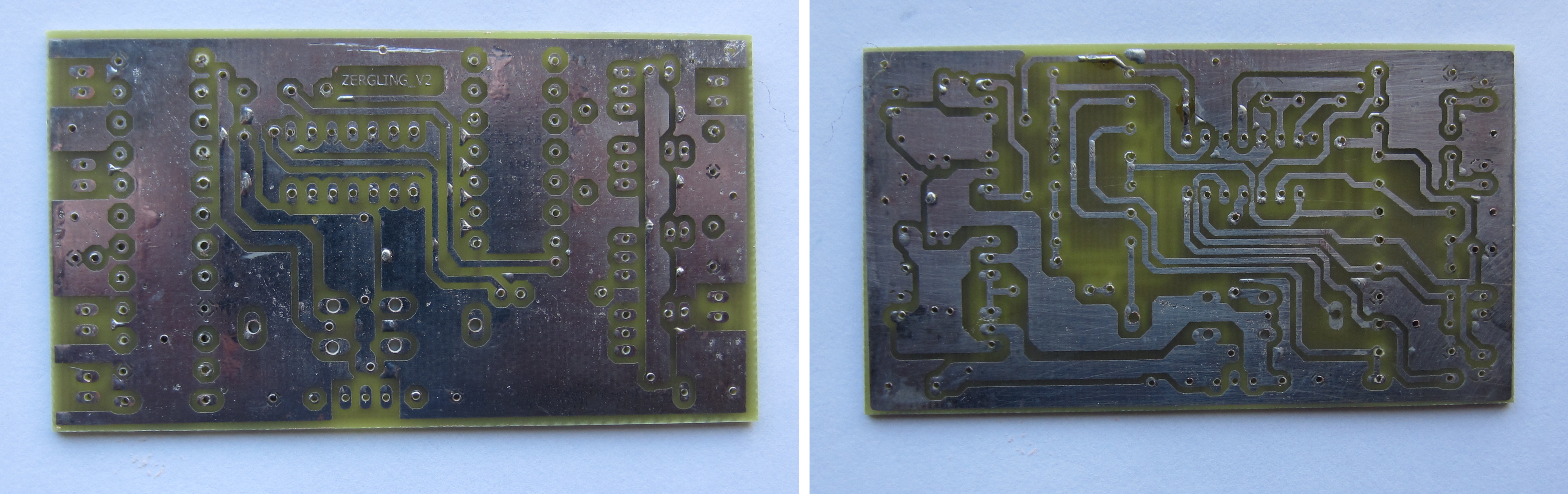
Figure 25 : PCB
Step 2: solder in the through board links or vias, these connect the top copper layer/tracks to the bottom copper layer/tracks. These links are make from standard single core wire, simply bend the end to form a 'L' shape, then push through the board. Solder the top, then turn over the board, bend the wire 45 degrees to lock it in place and solder the bottom, trim off any excess wire. To stop the link being pushed out when you solder the top i normally rest the PCB on the rubber handles of the wire strippers, as show in figure 26. Refer to figure 17 to find the position of the 'green' via holes.
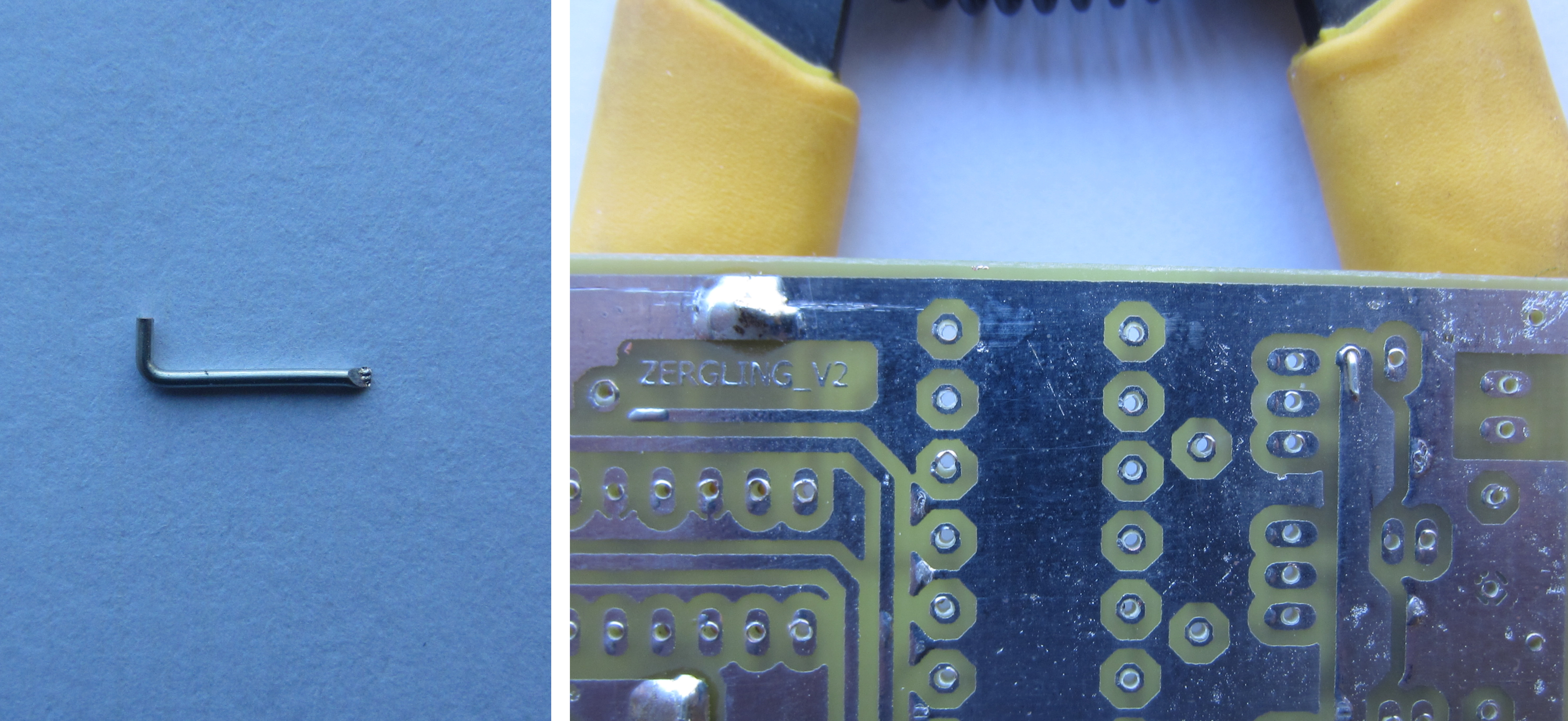
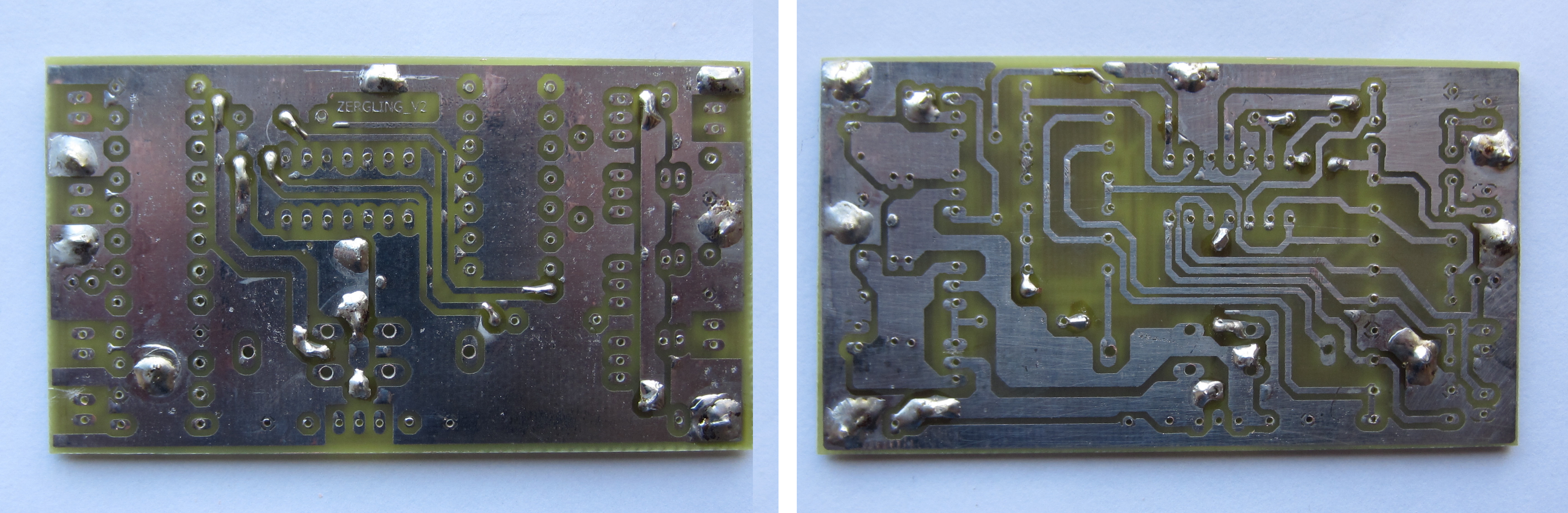
Figure 26 : VIAs
Step 3: solder in the resistors. Using a pair of needle nose pliers bend each leg of the resistor 90 degrees, such that it slides easily into its holes, as shown in figure 27. Push the resistor down such that there is a 1mm gap between the resistor and the PCB. Ensure the resistor is parallel to the PCB. Then solder into position, trim off any excess wire. Repeat for the diodes. Refer to figure 17 for resistor values.
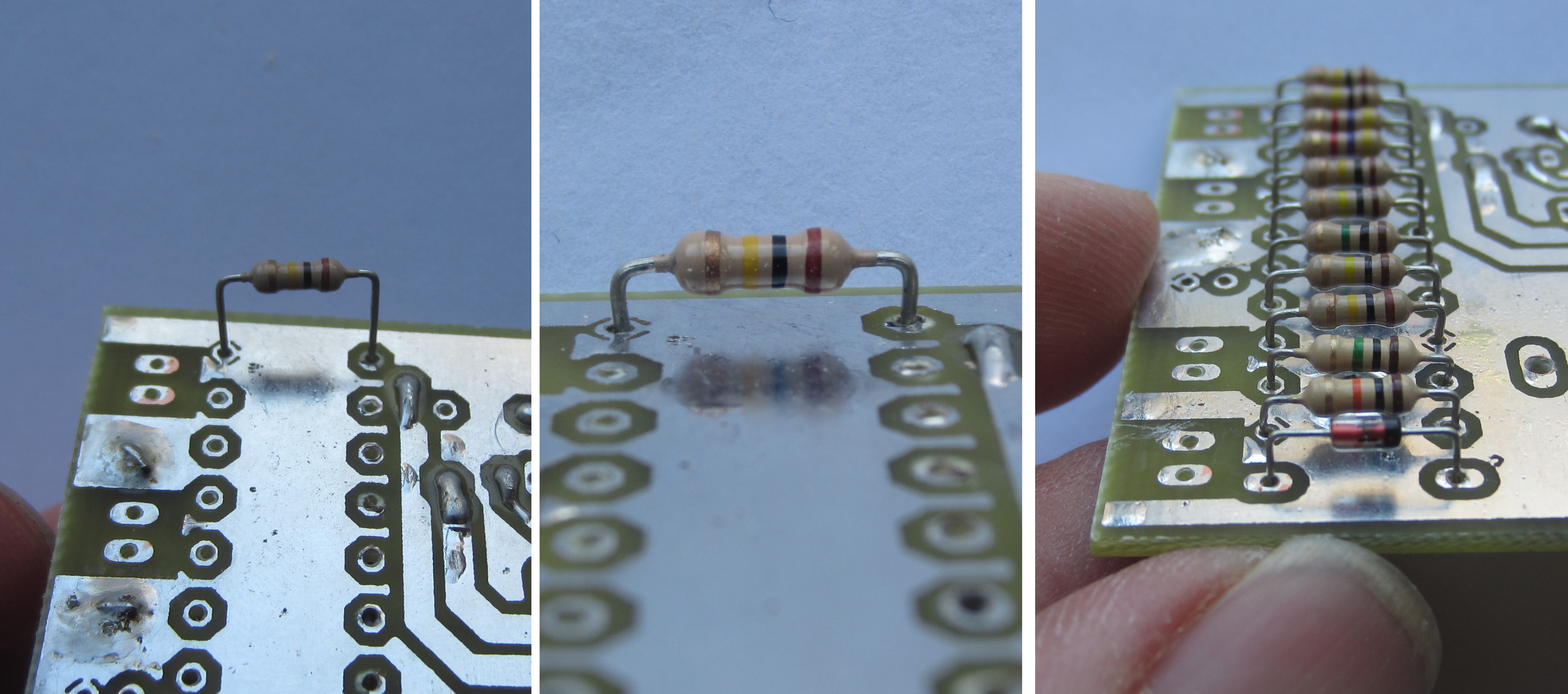

Figure 27 : Resistors and Diodes
Step 4: solder in the capacitors, as shown in figure 28 (forgot to solder in the front electrolytic in original pic). Some capacitor legs have a preformed bend, do not pull the leg tight onto the PCB as you may accidentally short out the top and bottom layers, always make sure there is a gap.
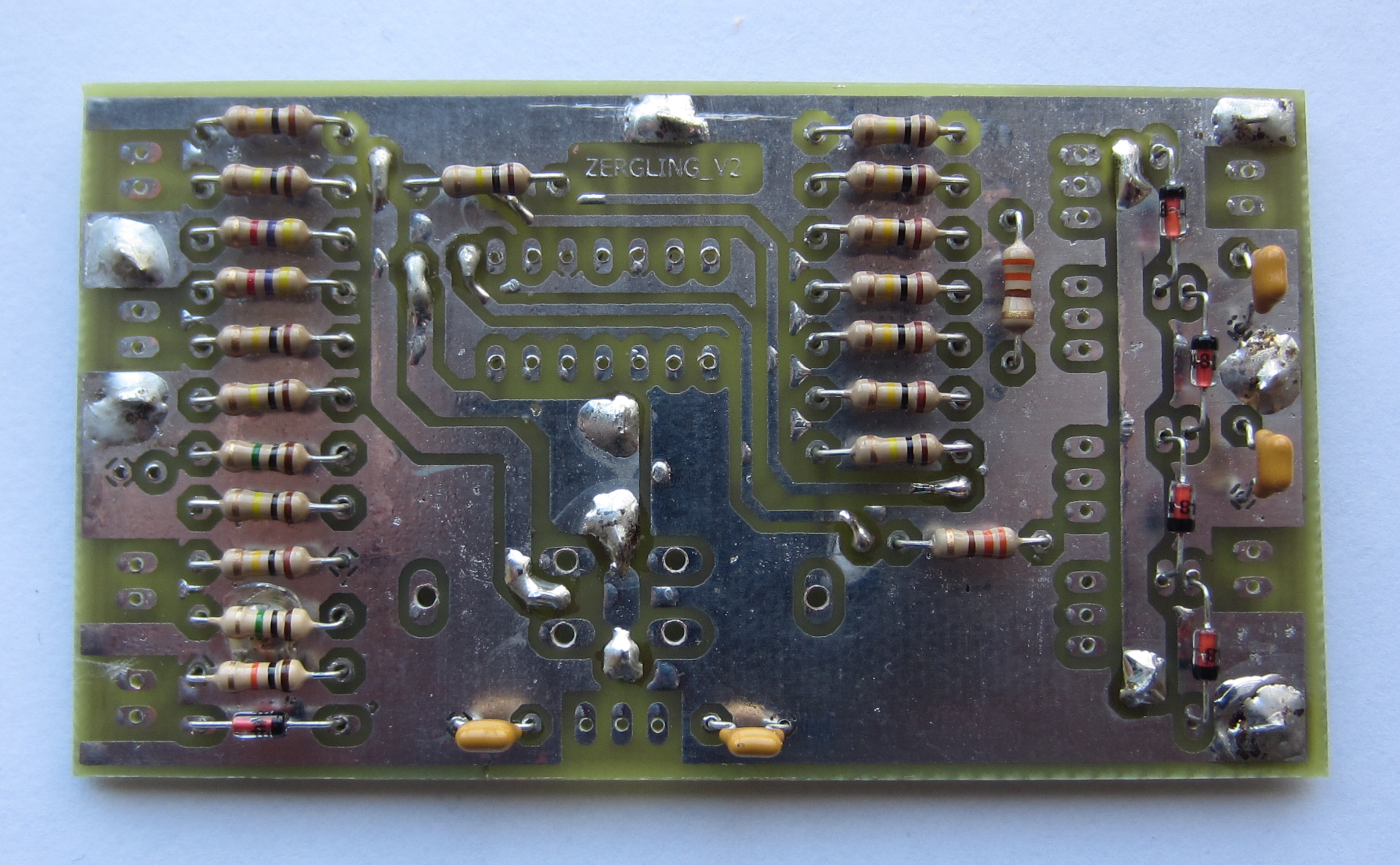
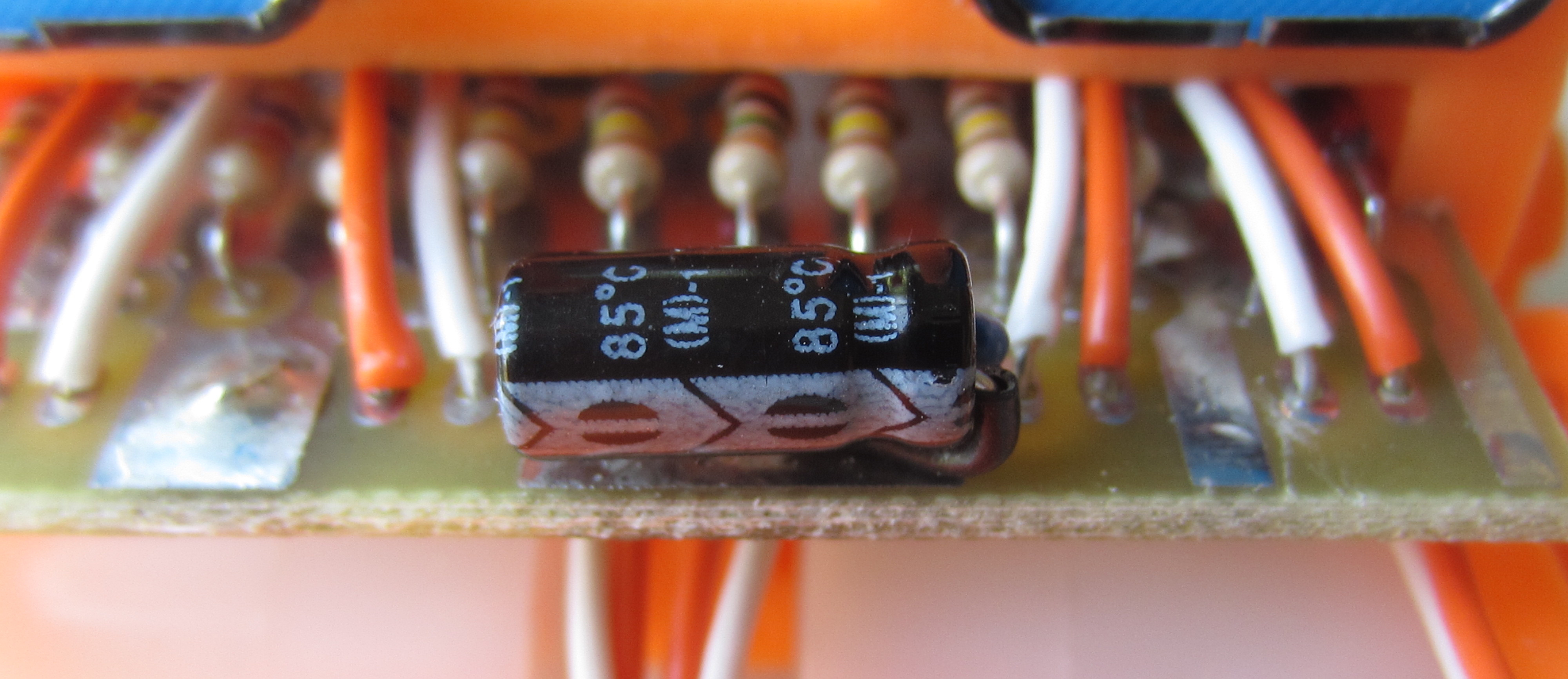
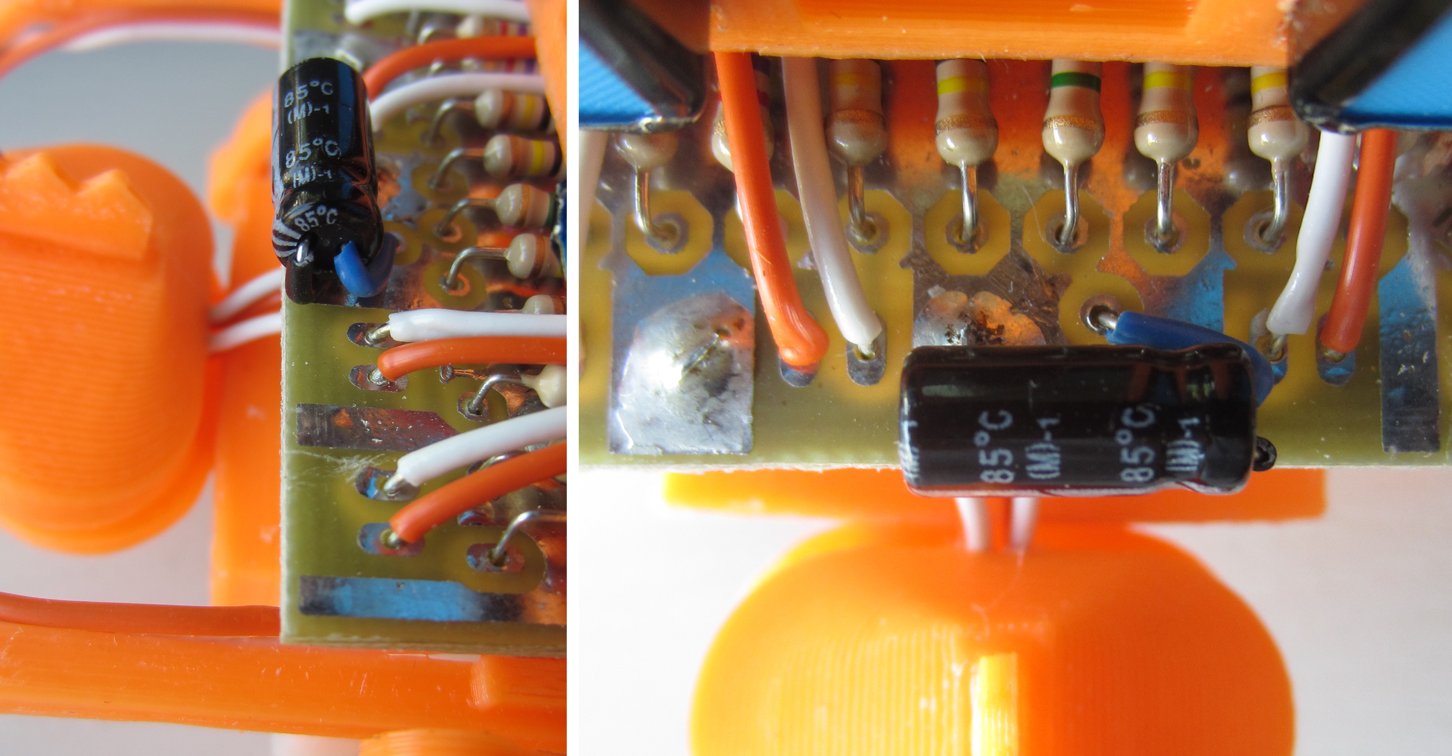
Figure 28 : Capacitors, ceramic (top), electrolytic (bottom)
Step 5: solder in the IC socket and pots (variable resistors), as shown in figure 29. Make sure there are no broken tracks or shorts under the IC socket, as once its in, its tricky to get off.
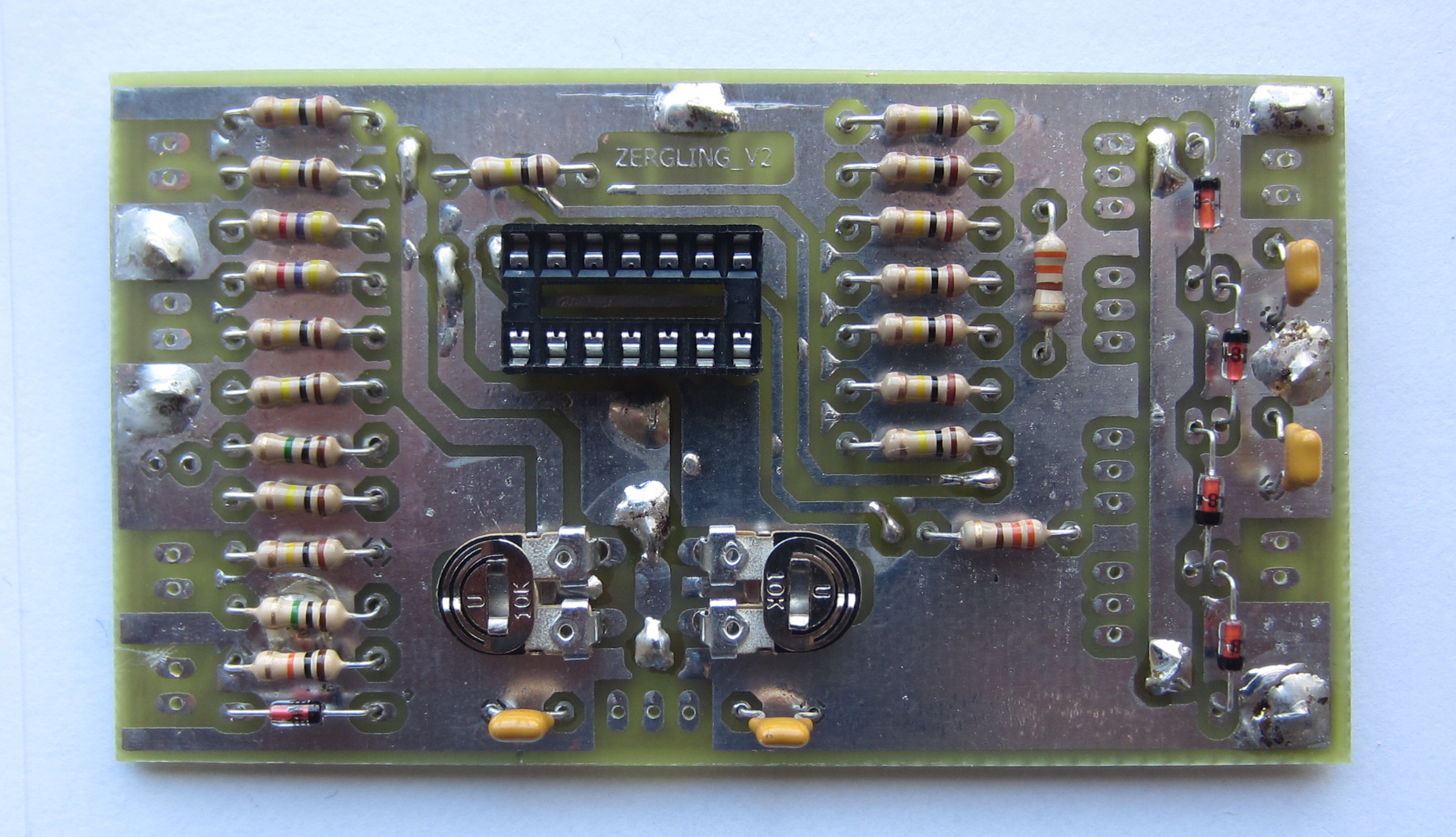
Figure 29 : IC socket and pots
Step 6: solder in the transistors, as shown in figure 30. When soldering semiconductors don't take too long i.e. don't overheat the device as they can be damaged by excessive heat. IMPORTANT: make sure you solder the right transistor in the right place, the right way round. BD136s in the middle, BD135s on the outer edges. Then insert the LM324 IC, you may need to gentle bend the legs a little so that it fits into the socket.

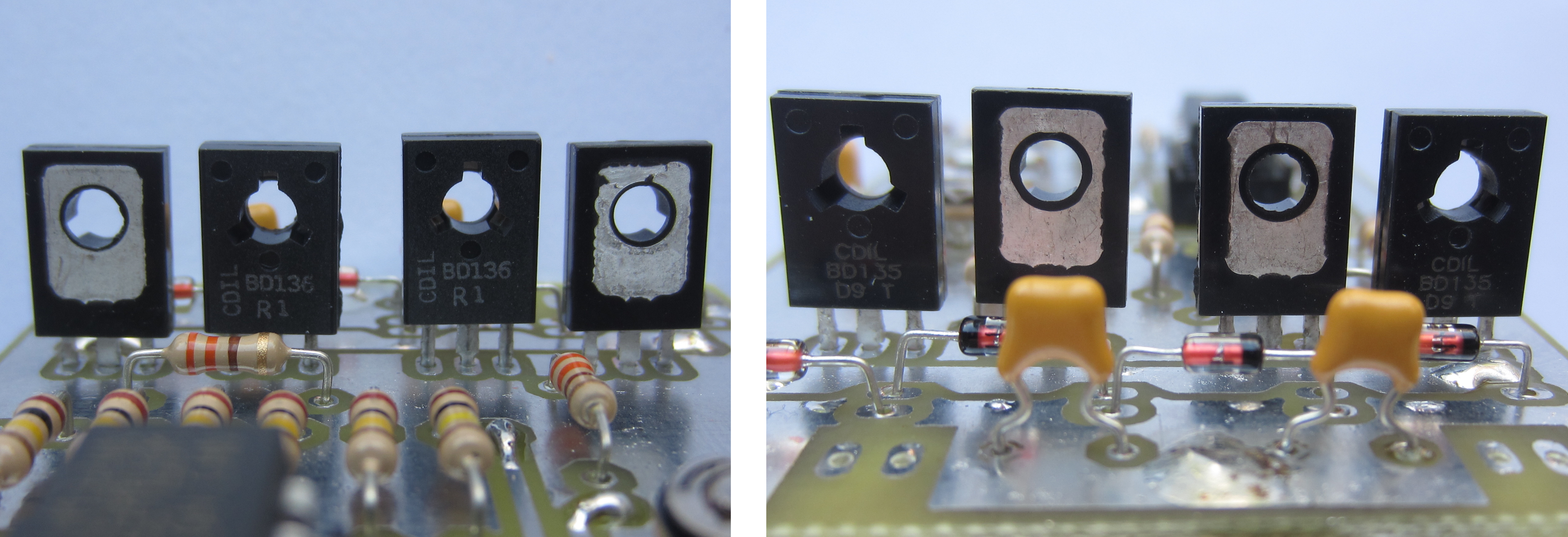
Figure 30 : Transistors
Step 7: IMPORTANT, read the assembly notes for version 2.1 first, there is a lot of information here: LINK, then go to step 8
Step 8: file off the flashing. During the 3D printing process the bottom layer tends to get pushed out, flattened i.e. it forms a lip. To allow the different piece to slot together these need to be removed using a needle file, scrapper, sand paper or a knife. When you have cleaned up all the pieces insert the two motors, as shown in figure 31. Make sure you file out the top slots that hold the PCB.
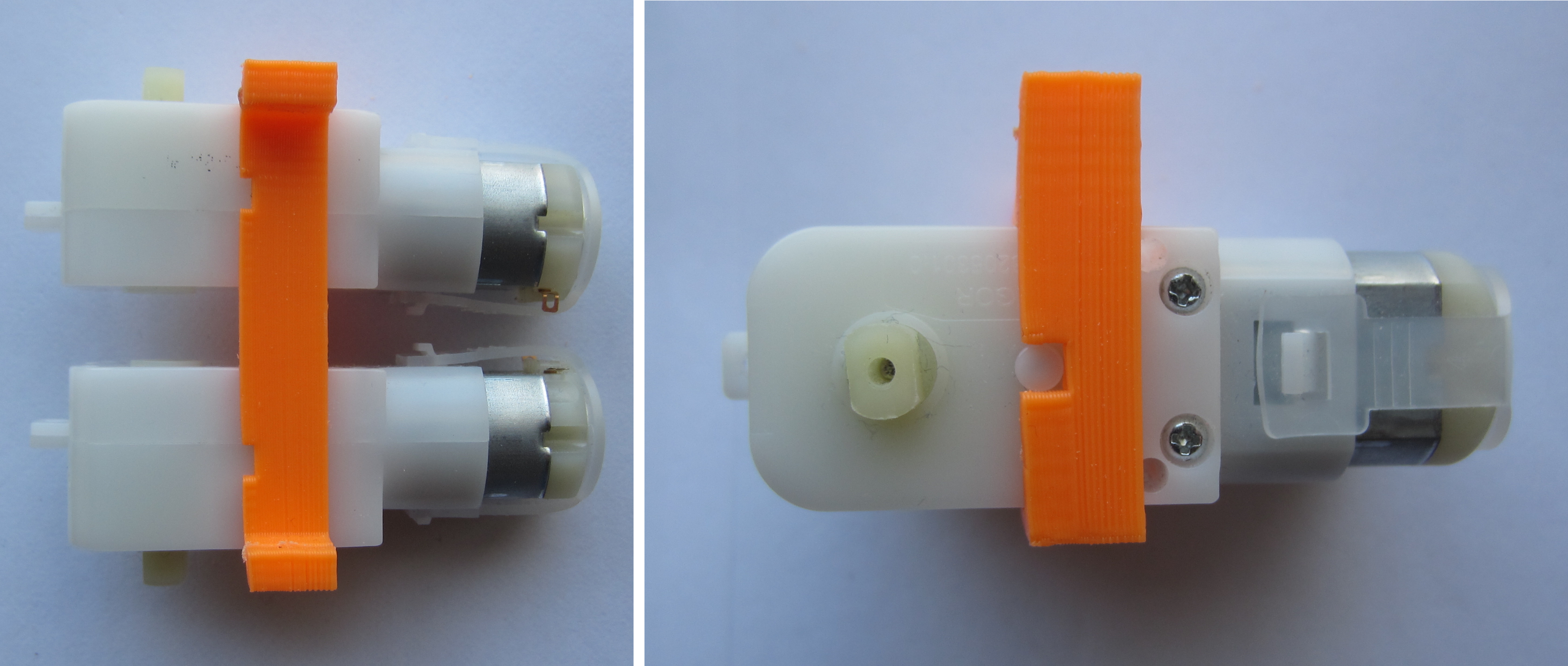
Figure 31 : Motors
Step 9: attach wheels, skid and neck, as shown in figure 32. Wheels are a push fit, you may need to bevel the leading edge a little to get them to fit. The rear skid slots into the main body, make sure the skid's 'slot' is filed open, should be a tight fit, don't normally need glue. The neck fits over the gearbox front pegs, this piece normally needs the most filing, again it should be a friction fit.
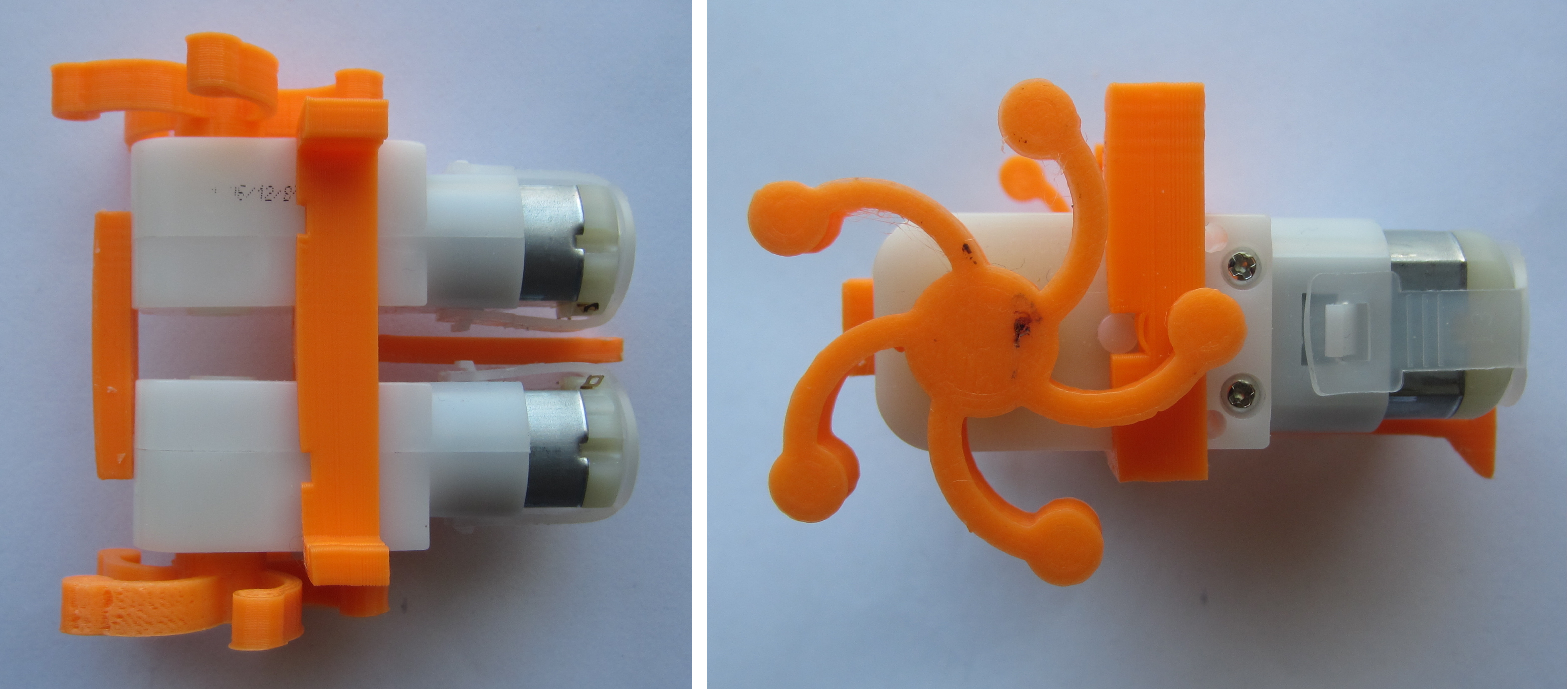
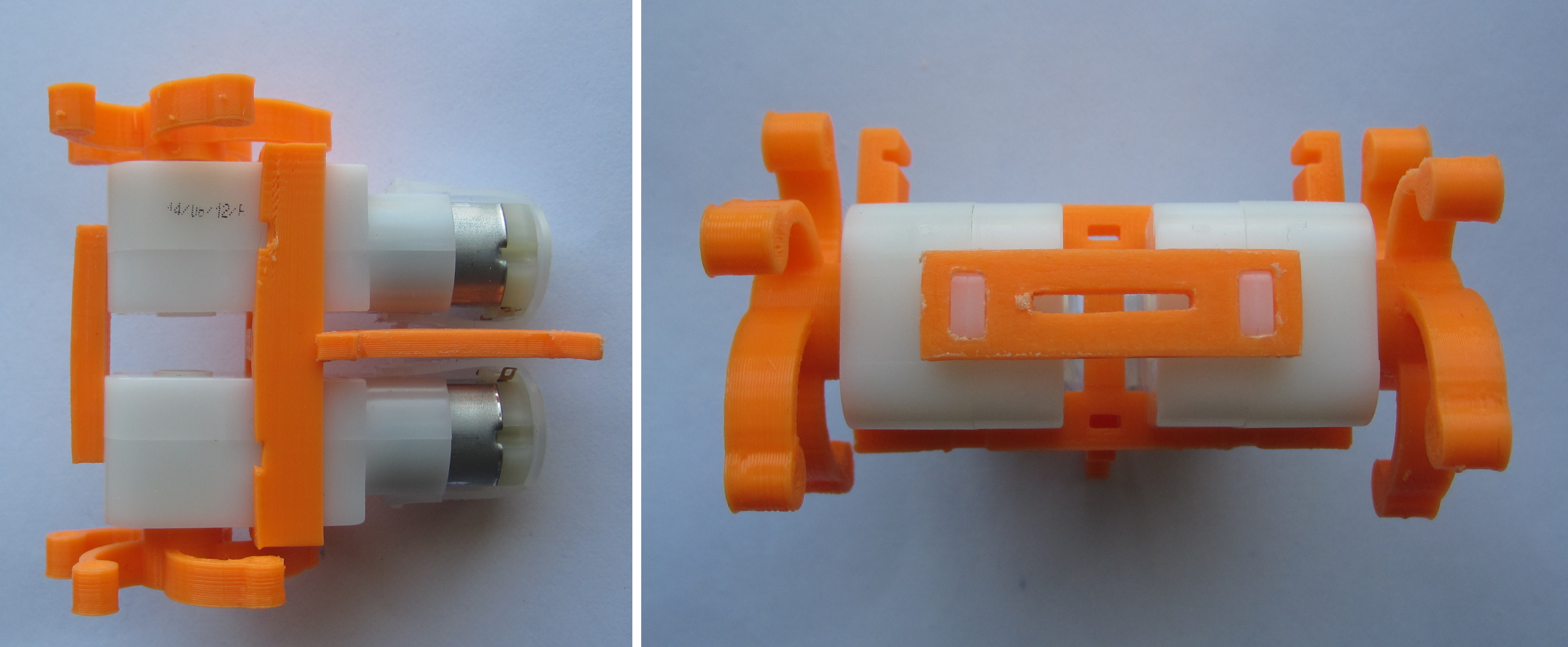
Figure 32 : Wheels, skid and neck
Step 10: wire motors, as shown in figure 33. Note, orange wire top, white wire bottom. Wires should be 90mm long, measured from the back of the motor. As described in the previous section (version 2.1), twist wires together.
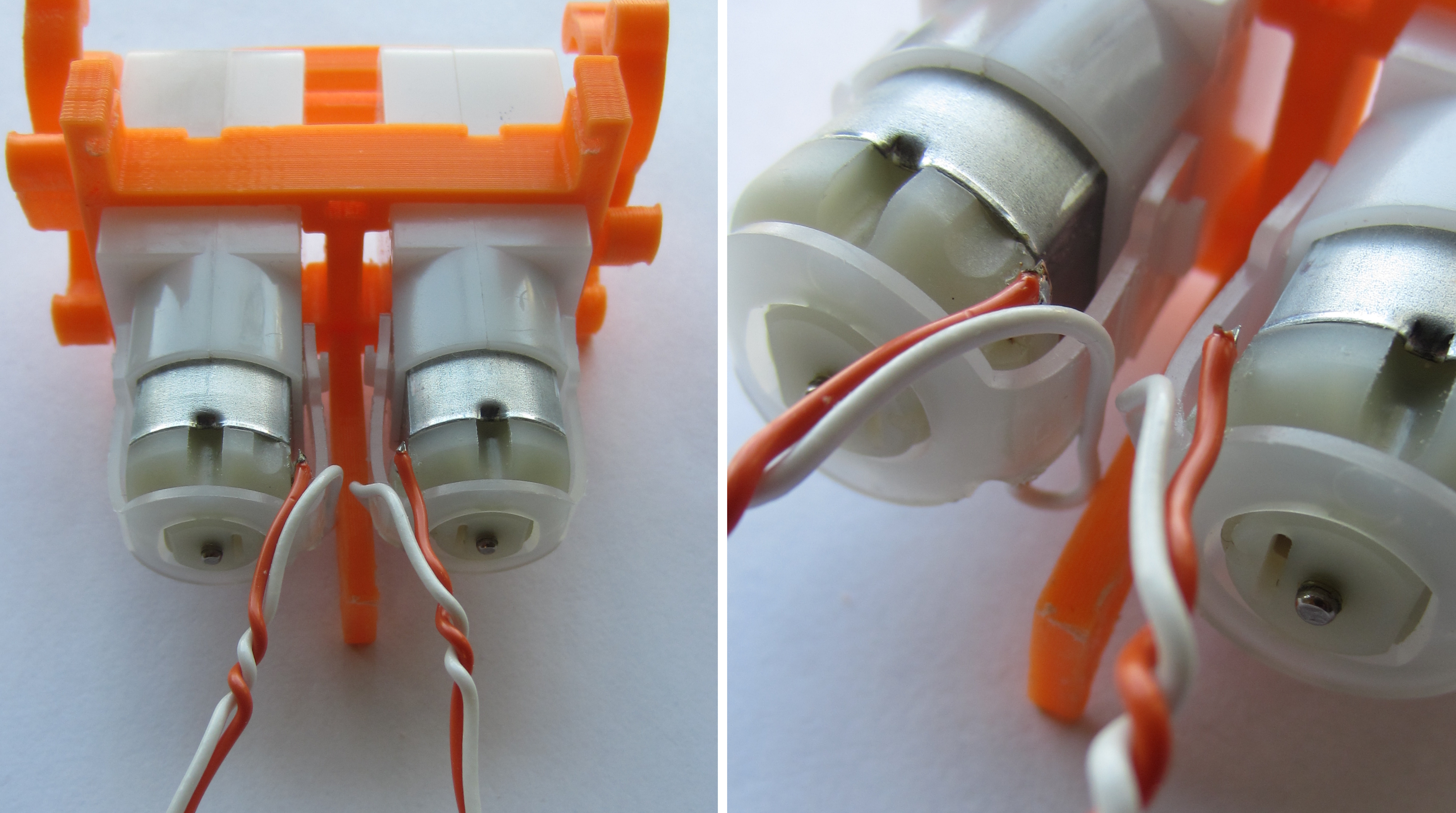
Figure 33 : Motor wiring
Step 11: assemble arms and fingers as described in the previous section (version 2.1). Super glue wires along arm, then super glue arm onto main body. You may need to file either the body section or the arm section to ensure they click into place without a gap. Note, solder orange and white wires to contacts, these should be 140mm long, measured from the back of the motor. Lower jaw is a push fit into neck, not normally glued.

Figure 34 : Arms and fingers
Step 12: power cable, solder two PP3 battery clips as shown in figure 35. Wrap insulation tape (single piece) around each solder joint, try to ensure there are at least two layers of tape between each wire, finally slip over a rubber sleeve to stop it unrolling. Wires should be approximately 50 - 75mm long, solder onto the PCB as shown in figure 36.
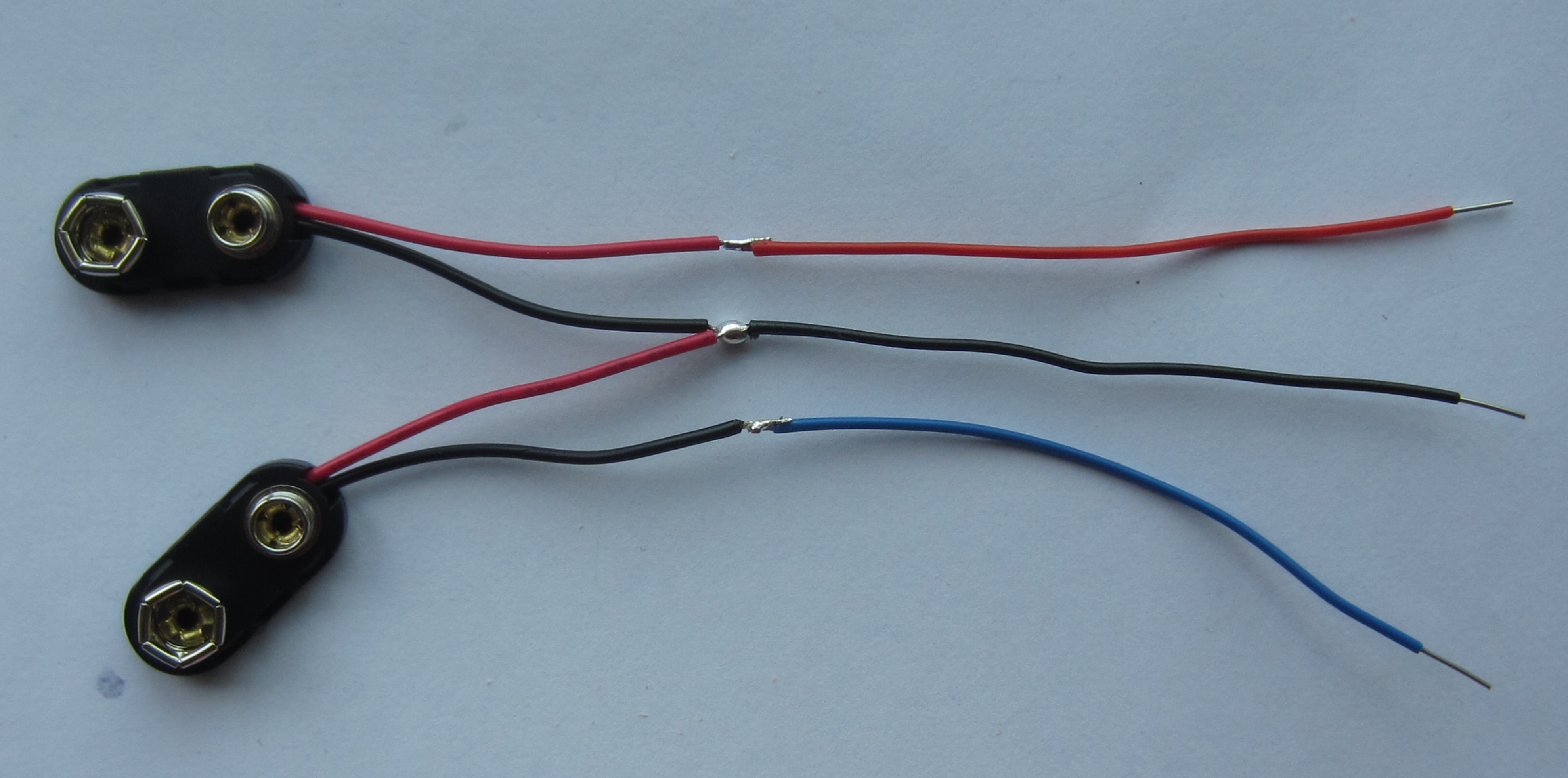
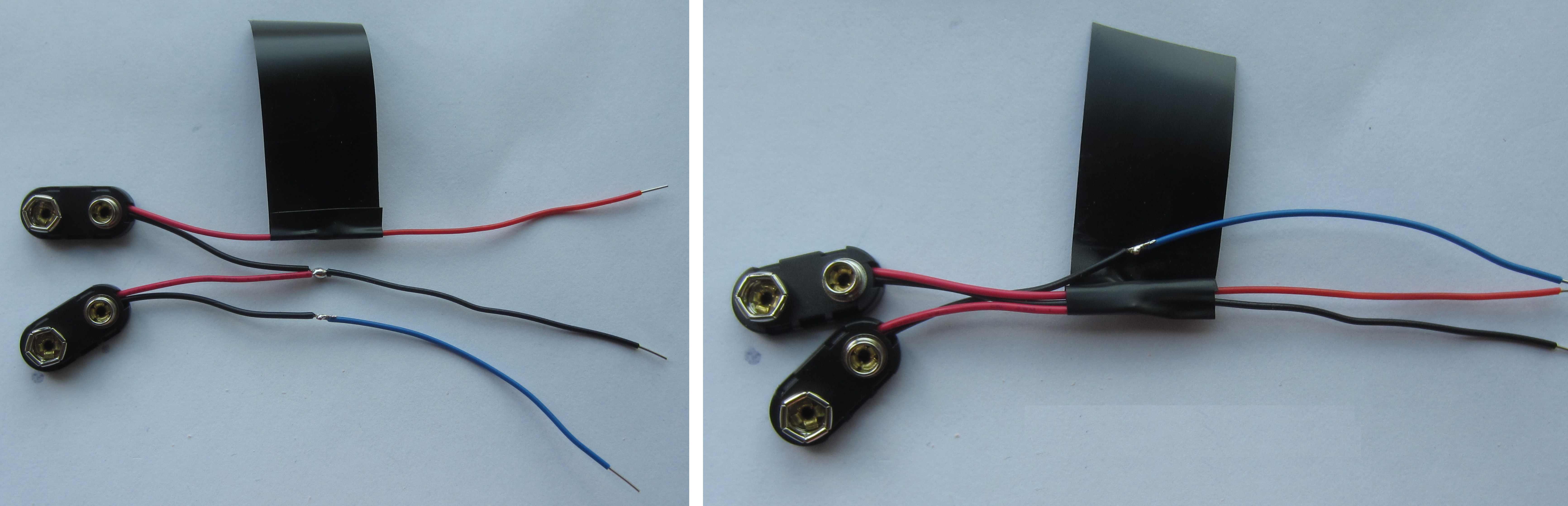
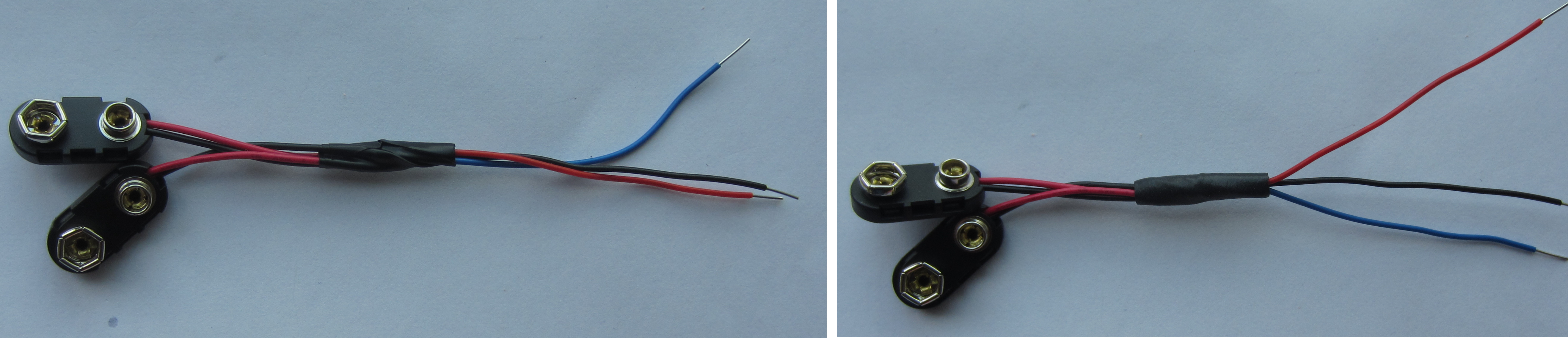
Figure 35 : Power lead
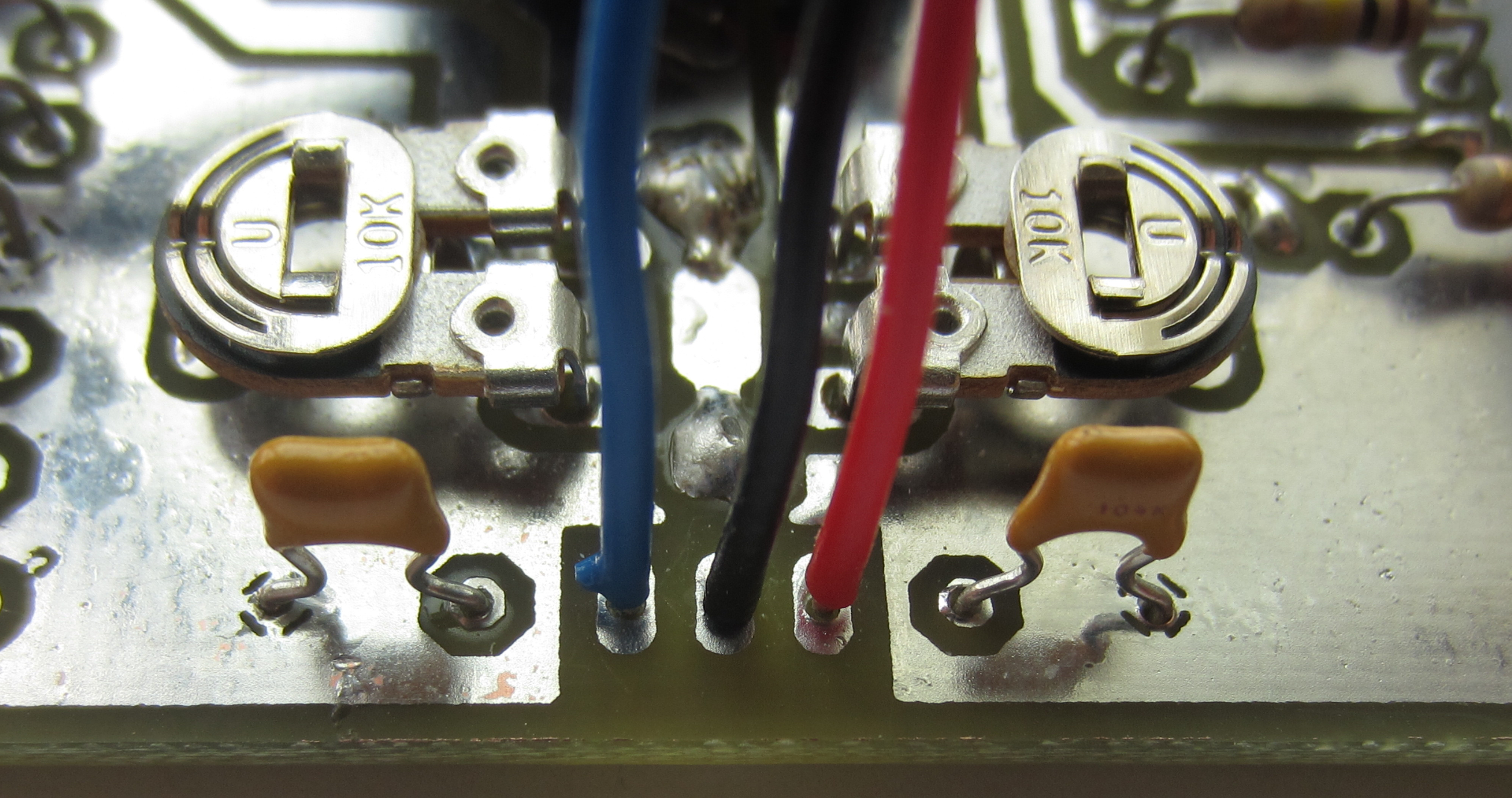
Figure 36 : Power lead on PCB
Step 13: glue on the head. A little super glue on the bottom jaw and the head, then hold in place until set. Note, bend the LDR wires up and run them back over the top of the robot, do make sure the wires coming out of the eyes in the top of the head are recessed into the channel, otherwise you will not have a flat surface to glue. Once set i did drip another drop of super glue either side and allow it to run into the joint. Leave to dry, go get lunch, otherwise it will just snap.
Step 14: the left and right side of the robot are defined with the robot facing you i.e. when its looking at you. Motors, LDRs and bumper switches should be wired to the PCB as shown in figure 37. As the PCB has to slide into the main body side clips the motor wires need to be 90mm long (allowing it to move backwards). The other wires should be feed backwards and around the side of the PCB. Depending on where these wires are soldered, some wires may need to be trimmed slightly shorter than their original 140mm. If you wish the Zergling to seek the light rather than darkness you should swap over the LDR signals i.e. solder the Left LDR wires into the Right LDR's holes and the Right LDR wires into the Left LDR's holes.
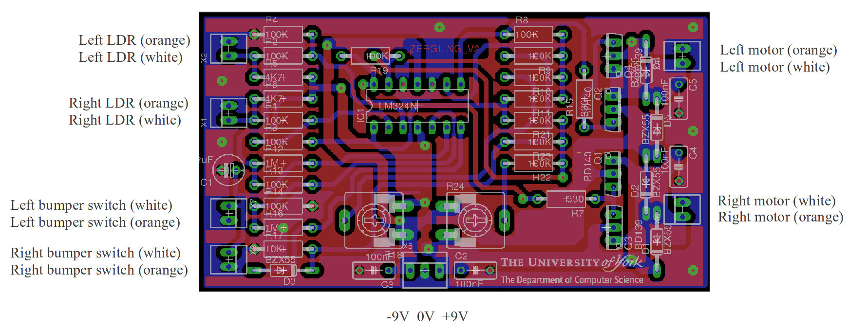
Figure 37 : Wiring (update 5/6/16 motor wire error)
Step 15: mounting the PCB, bend down the LDR and bumper wires, then slide the PCB into the main body slots, position the battery bracket such that as the PCB slides out of the main body slot it continues into the battery bracket slots, as shown in figure 38.
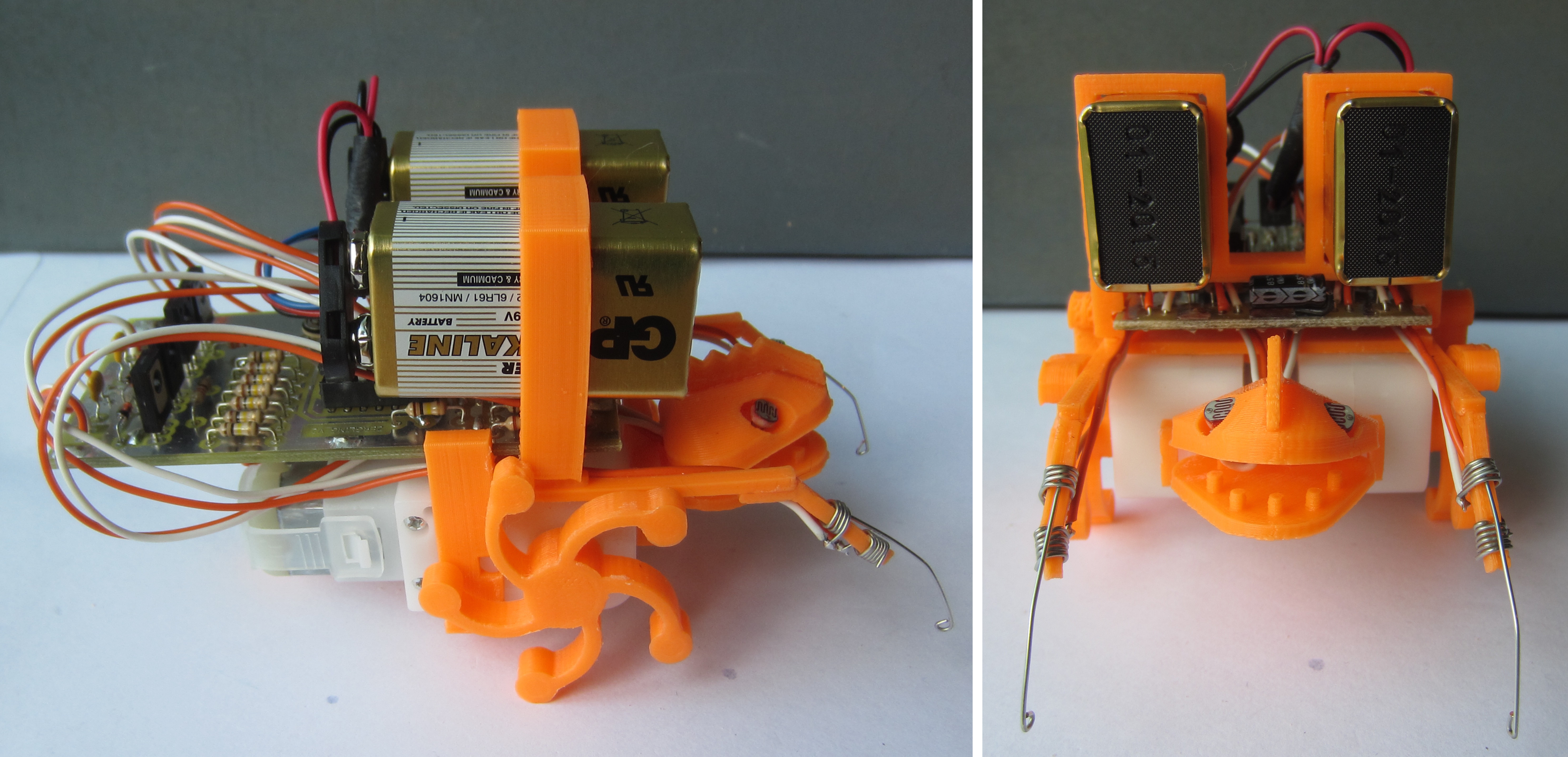
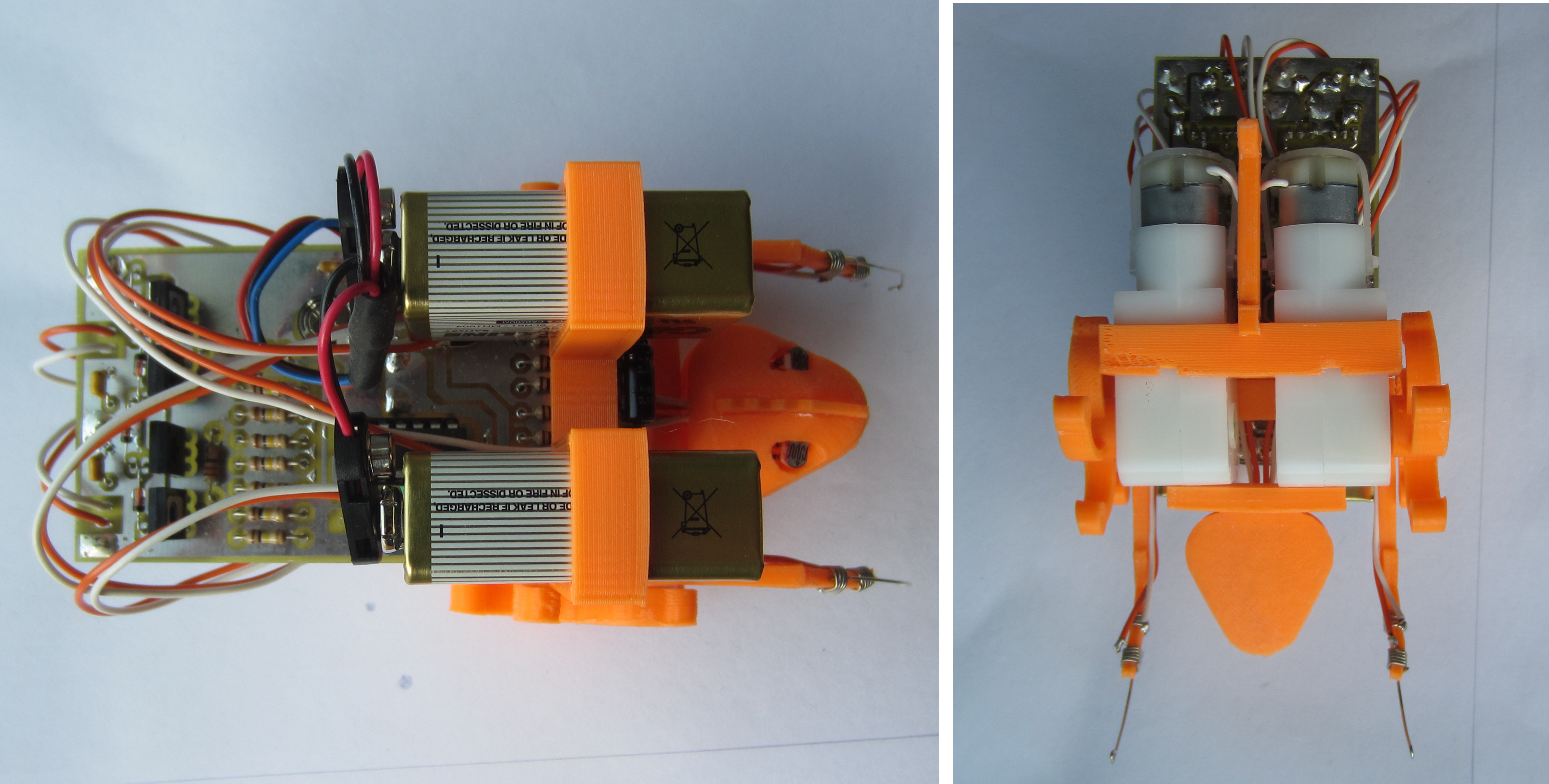
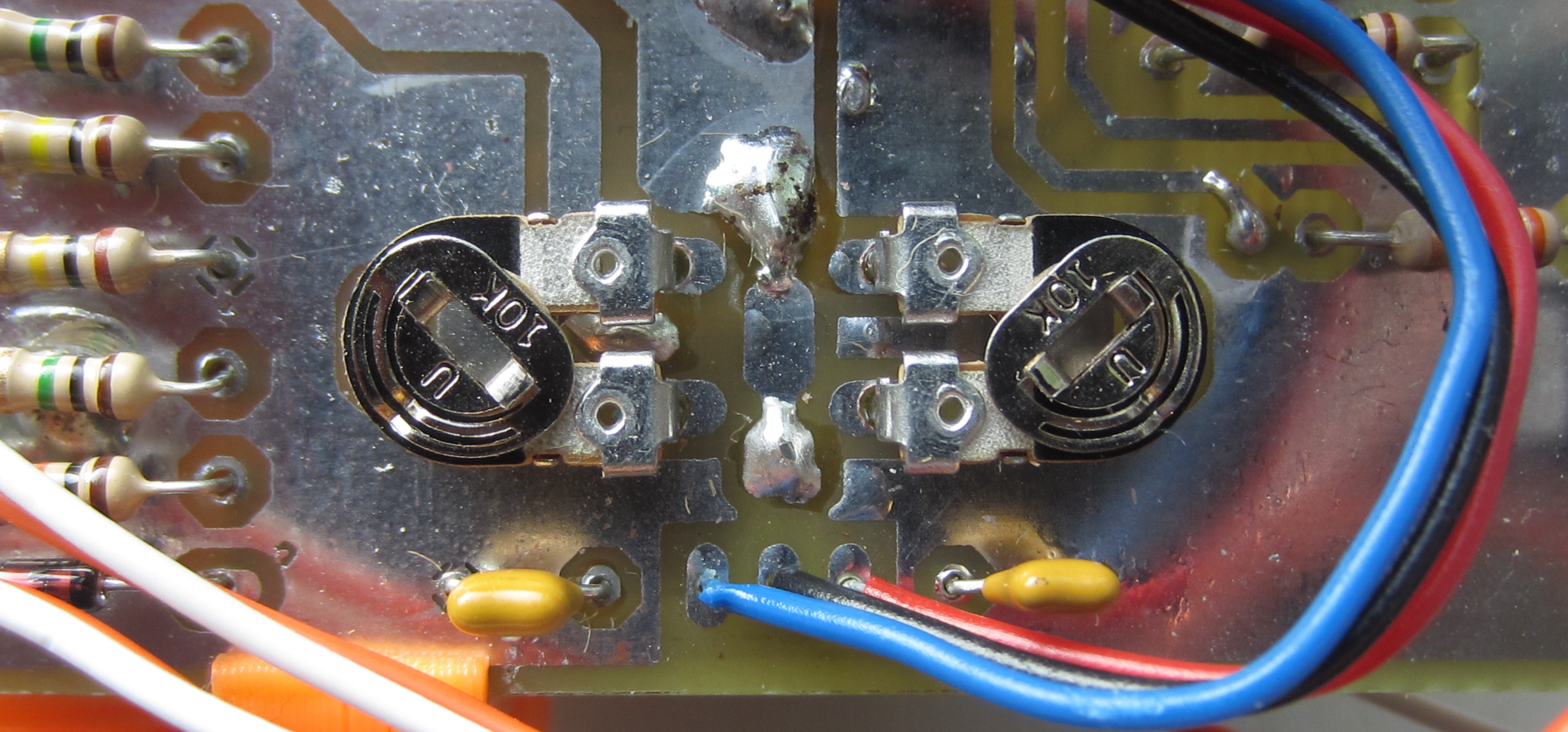
Figure 38 : Final prototype zergling (top), pot settings (bottom)
Step 16: final assembly and testing. Push two PP3 +9V batteries into the battery bracket with their negative terminals upwards. Clip the battery clips onto only the bottom terminals i.e. angled inwards. This allows the clips to be used as switches, rotating them upwards makes contact with the negative terminals, completing the circuit. With the batteries connected and with the two LDRs covered adjust the two pots such that both motors rotate forwards at a slow speed (as shown in figure 38). The speed of the two motors should now be controllable by varying the light levels falling onto each LDR. The robot should also rotate on the spot if a bumper switch is pressed. If the robot continuously rotates, one of the bumper switches will probably need adjusting. Here is a video clip of the robot in action, LDRs are wired such that the Zergling will avoid the light, seek darkness : LINK, LINK, LINK (had troubles with some browsers, video/sound ok when downloaded). This is definitely a desk top toy, not really an all terrain robot. On rough surfaces e.g. carpet, the rear skid creates too much friction, need something smooth, with a larger surface area so that it does not sink down into the pile/fibres e.g. a large bead. As the rear skid is not glued in will see what i can find i.e. a changeable rear foot for different surfaces.
I'm sad to say that the Zerglings will never rule the Earth and are heading for an early death :(. The unfortunate truth is that cheap batteries never last long. When i was designing this robot i was looking at using Kodak 9v Zinc Batteries (pack of 2) from a pound shop of your choice, datasheet here: LINK. This is a 500mA/h battery (well thats what the marketing says). When in operation the current taken from each battery is 10mA standing still, 50mA when walking, 100mA when turning quickly and a lot more if its walking up hill or if the motor are stalled. So how long will your Zergling live? Hmmm, I found a more interesting datasheet of a similar battery, the Energiser (522) LINK. This shows that the total Ampere/hours is actually dependent on how quickly you discharge the battery i.e. 500mA/h is an average, if you discharge at 500mA the actual battery will not last an hour. Also at this point the voltage will be a lot less than 9V. Some interesting graphs are shown below.
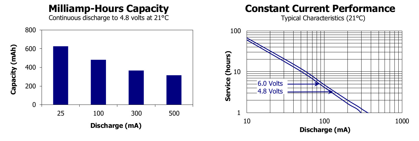
Figure 39 : Battery life
Therefore, hard to guess our Zergling's a life expectancy, i would say 1-2 hours, so enjoy every last rampage. Alternatively you could go Lithium LINK, which would match the explosive nature of a Zergling, but they are a lot more expensive, probably looking at £4 to £8 each. For long term mayhem, probably best to go to rechargeable, Nickel Metal Hydride LINK, but again probably looking at £3 to £5 each. What would be nice would be to adjust the Zerglings behaviour to include recharging e.g. solar panels, such that it would seek light, but when it finds a good spot it would stop and 'eat', only moving when the light moves.
If you building this as part of the week 8-10 activities, like all good toys batteries are not included, my budget ran out :).
As not everyone can make PCBs have layout a Veroboard (strip-board) implementation using VeeCad as shown in figures 40-46. Roughly 18x38 holes, so should be the same size as the PCB. A pdf of the schematic, its netlist and VeeCad layout file are available here: (LINK) (LINK) (LINK). Note, to save space there are a couple of stacked links i.e. a short link under a longer link, or resistor. These will need to be insulated i.e. keep the plastic sleeveing on the wire. The netlist was generated from the original Eagle schematic so the component labels are the same. The power and LDR connectors are at the top (x5, x1 & x2), bumper switches are in the middle (x3 & x7) and the motor terminals at the bottom (x4 & x6).
WARNING: i have not tested this layout. As space was limited didn't try to separate Motor and Circuit power rails, which will make it a little noisy. However, i suspect it will be fine.
UPDATE (4 June): constructed a veroboard zergling, worked fine, a little longer than the PCB versions.
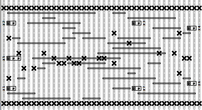
Figure 40 :VeroBoard - track breaks, wire links (level0), & connectors
Best to cut the track breaks (X) first as if you have soldered next to a break its a lot more tricky to cut i.e. you will need to cut through the solder as well, which can push the hole off centre. I normally remove the insulation on Level0 wire links to reduce the final height / save space e.g. under the IC socket. Connectors are just place holders were wires will be soldered later. Note, the top and bottom rows of Xs are just used to indicate the edge of the board i.e. i normally cut though these holes on the guillotine, or cut along using side cutters.
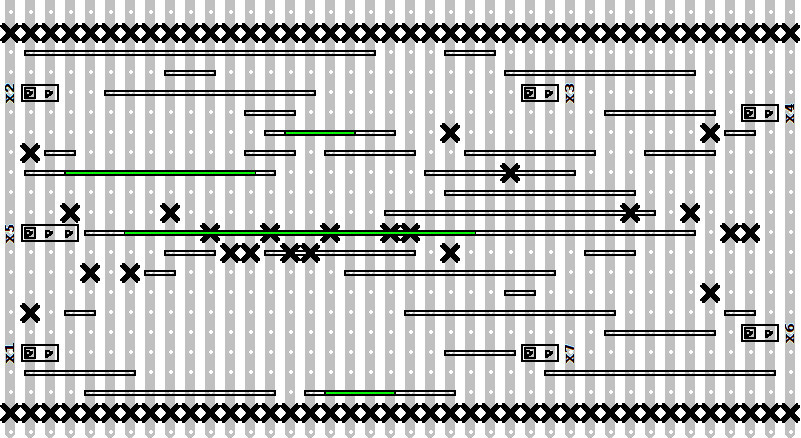
Figure 41 :VeroBoard - wire links (level1)
The green wires in figure 41 indicate level0 wire links. Level1 wire links are above these. These will need to be insulated to prevent shorts. Longer wire links e.g. running under the IC socket can be routed side-by-side rather than directly on top to reduce height. However, there is normally enough space under turned pin sockets.
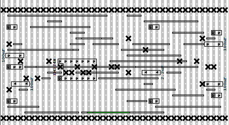
Figure 42 :VeroBoard - wire links (level2), IC socket & Capacitors
The green wires in figure 42 indicate level0 and level1 wire links. The Level2 wire link is above these. Again this will need to be insulated to prevent shorts.
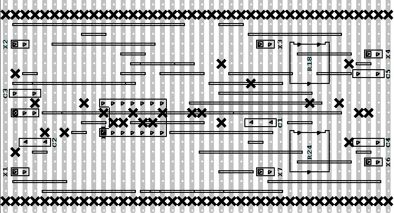
Figure 43 :VeroBoard - variable resistors (pots)
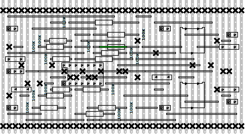
Figure 44 :VeroBoard - 100K resistors
The green wire in figure 44 indicates a level0 wire link under a resistor.

Figure 45 :VeroBoard - 330, 4K7, 10K & 1M resistors
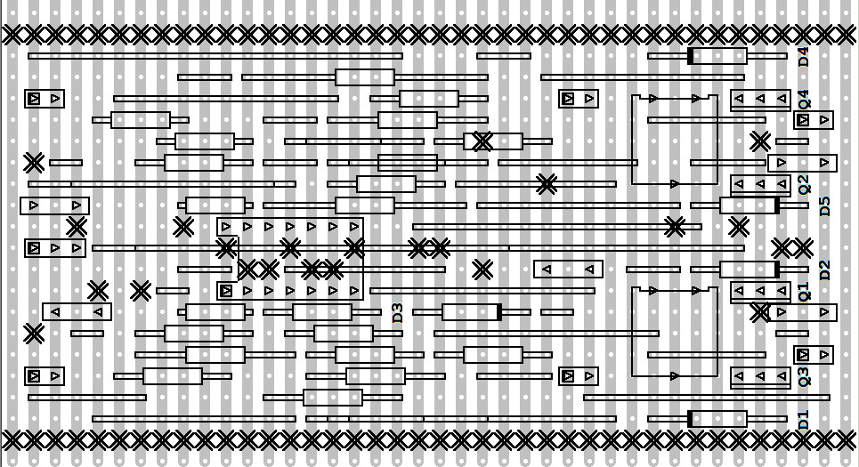
Figure 46 :VeroBoard - diodes and transistors
Note the diode direction, the black bar indicating the cathode. To be honest, the signal diodes are perhaps a little on the small side, however, the ones ordered do quote a max current of 300mA and peak voltage of 150V, which seems reasonable. Transistor are mounted vertically, orientation indicated by the rectangle i.e. the metal back. If your not sure refer to the datasheet to identify which pin is the base lead, this will be connected to the 330 ohm resistor.
Actually not sure if it is easier than gluing, but it fun. Insert approximately 2-3cm of plastic rod into a small hand drill, turn on, then apply a little pressure with the tip on the area to be welded. The heat generated by the rotating plastic is enough to 'weld' the two surfaces together. Note, as the plastic melts don't forget to feed the plastic rod slowly into and along the seam. Also like any welding be careful to avoid blow-through i.e. don't press too hard when you have a bead of molten plastic formed as you will just cut through the surfaces you are trying to join. You will need to replace the 'welding' rod as it wears down, you may need a pair of pliers to remove the remains of the old rod from the drill. Don't be tempted to insert an excessively long rod as it will be difficult to control. Here is a video of me assembling and welding the main body elements (LINK), be warned its 33 minutes of non-stop fun and excitement :)
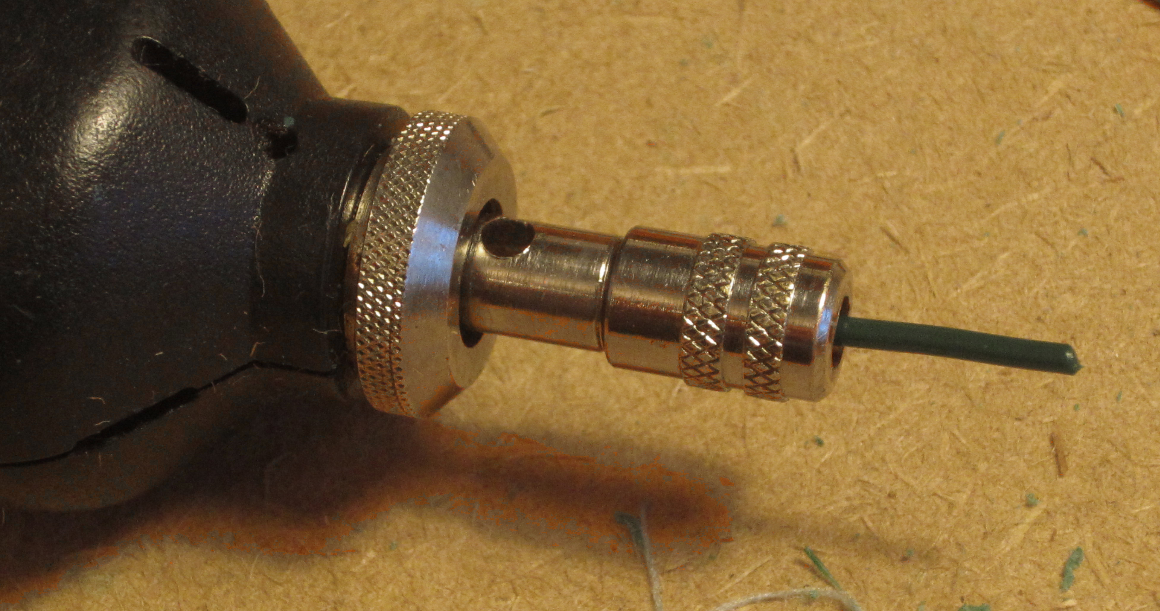

Figure 47 : plastic rod + drill
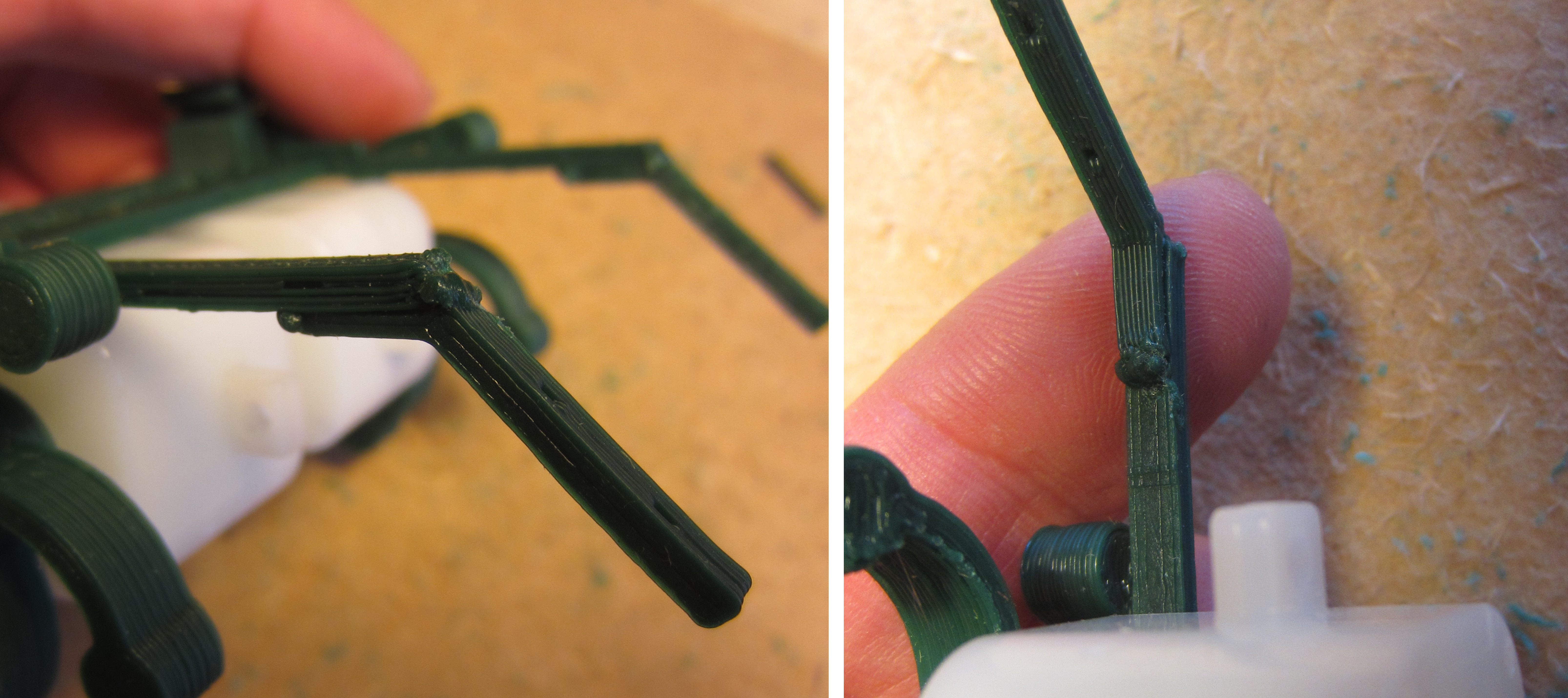
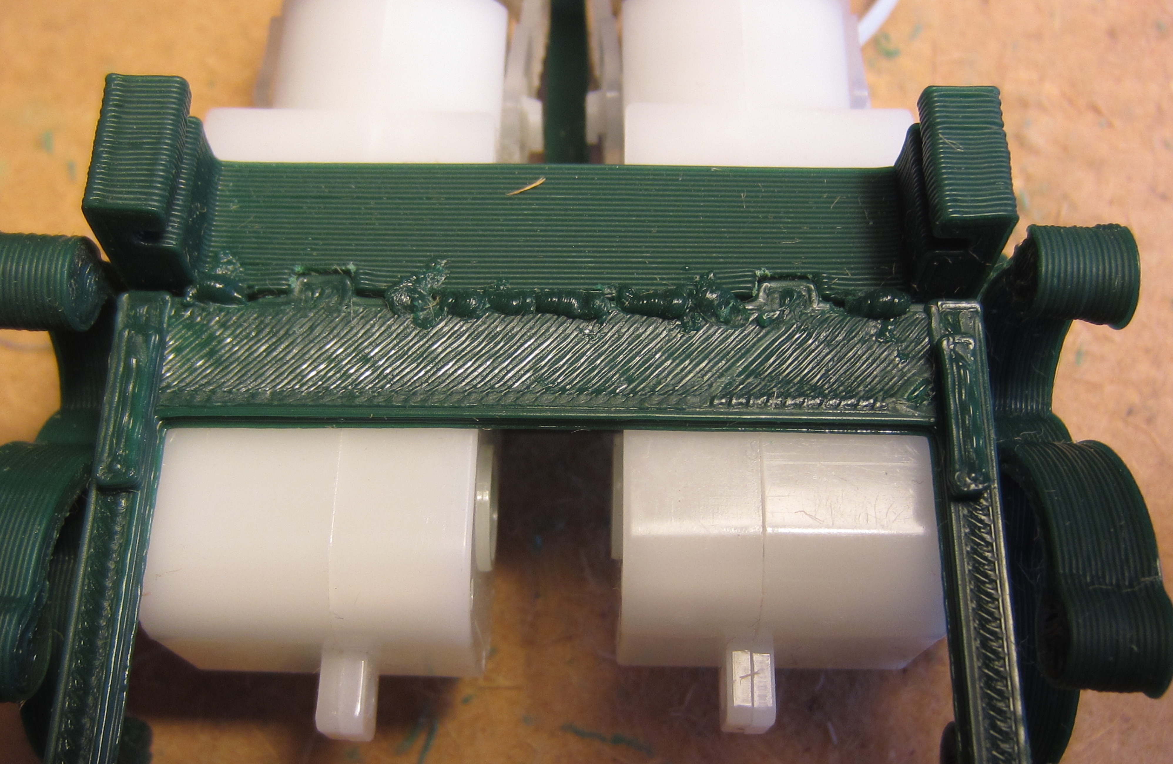
Figure 48 : friction welding
In summary, on the plus side friction welding is definitely faster than gluing, also if you are trying to joint two pieces of plastic with a very small contact area welding is a lot stronger. However, for the Zergling we do have reasonable contact areas, so strength is not an issue. Some web pages say that PLA can not be glued, but i always found super glue works fine i.e. once dry the plastic lamination's fail first rather than the glue bond. However, super glue does need a few hours curing to reach its full strength. On the negative side, friction welding can be a little messy and there is the danger of melting the parts.
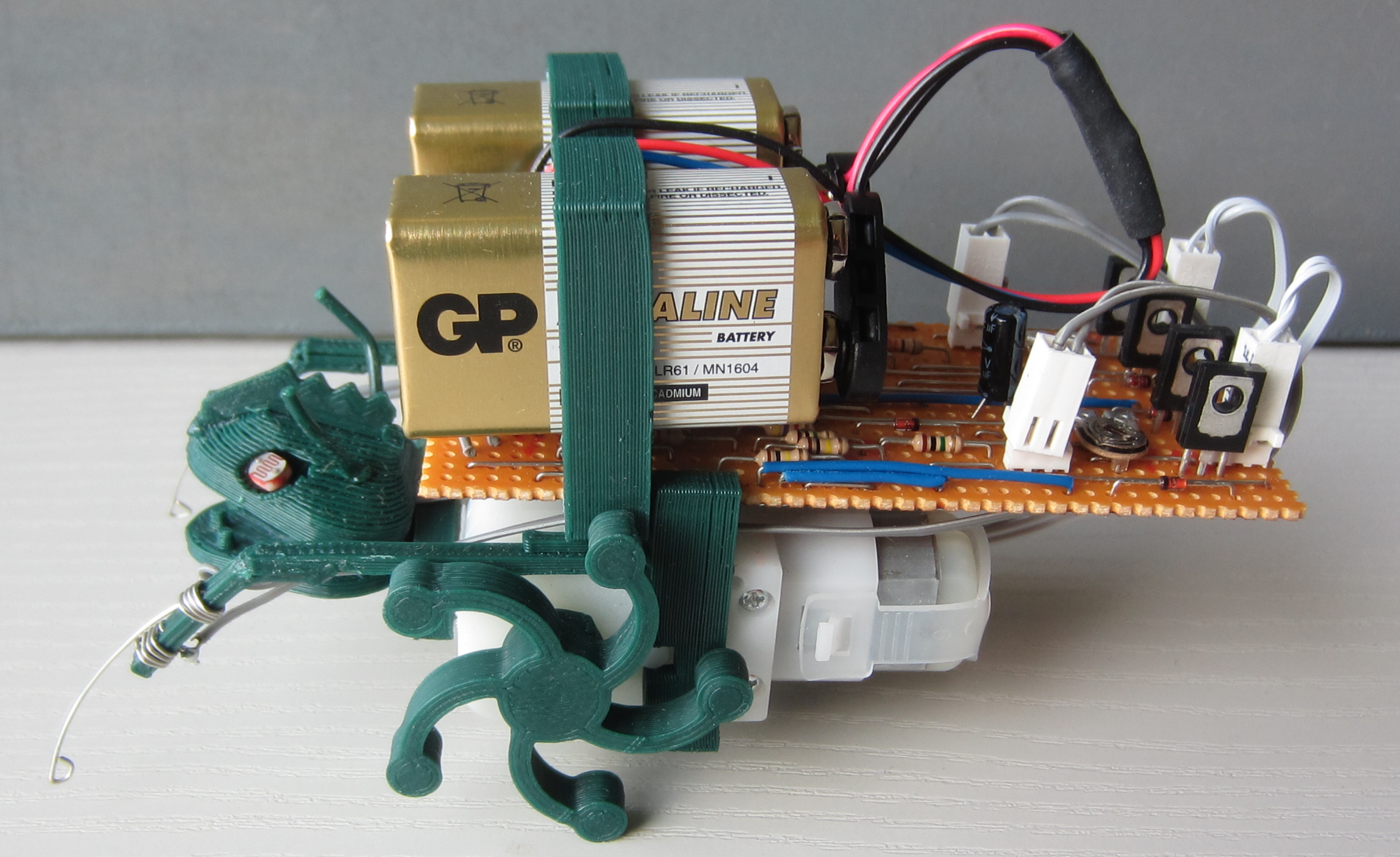

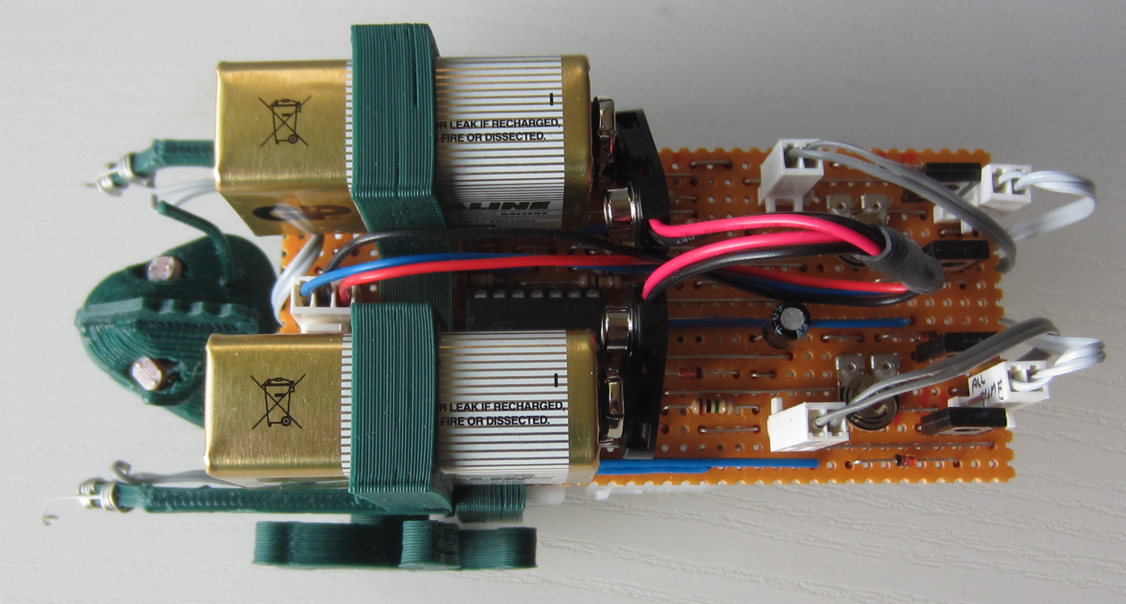
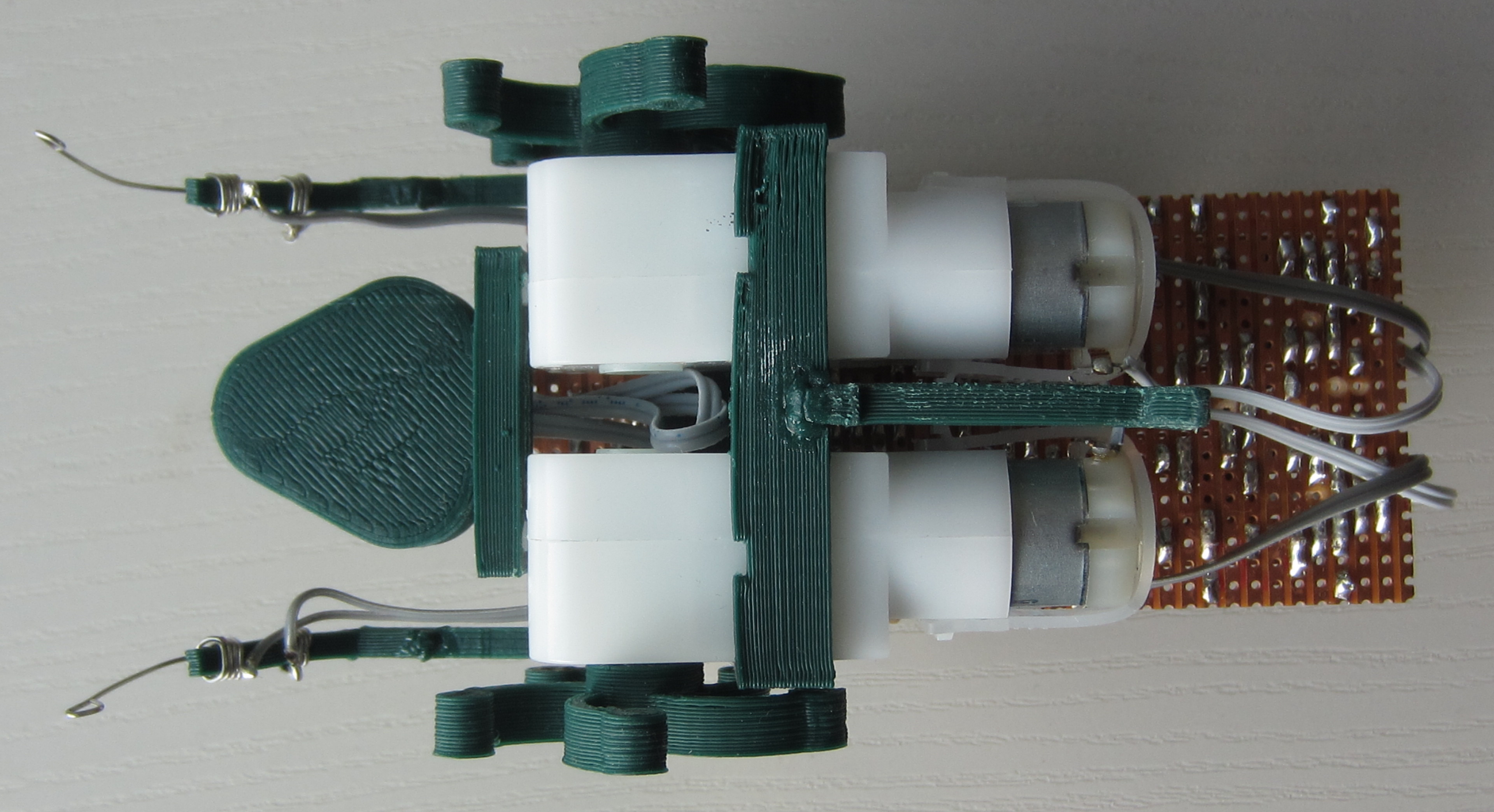
Figure 49 : veroboard Zergling
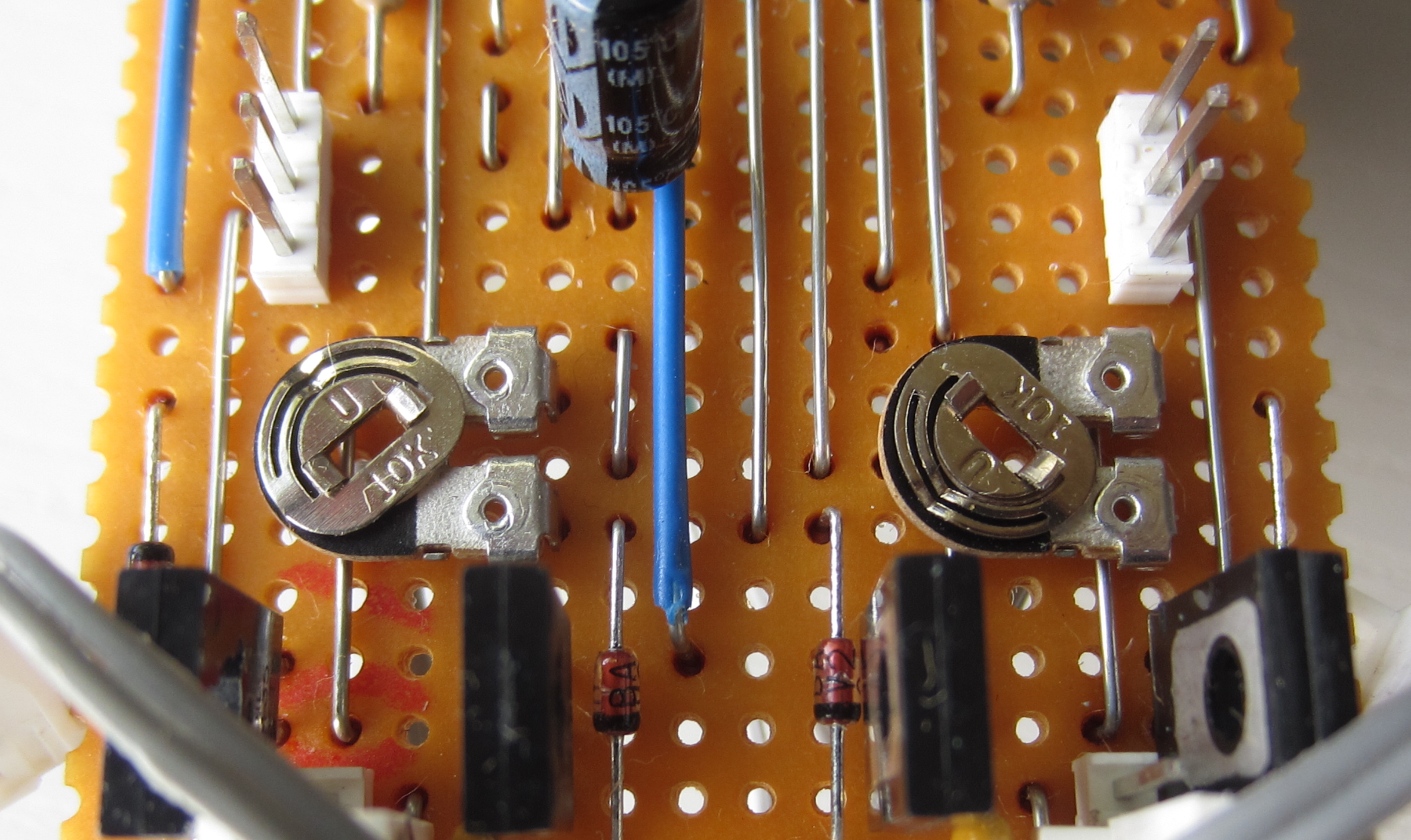
Figure 50 : veroboard Zergling pot settings
The final PCB has arrived, always that nagging doubt that there is an error in the PCB, fortunately all is well, the final version is shown in figure 51. Same design as the previous in-house PCB prototype, with the addition of a silk screen and through plated holes/vias. The only real difference is the electrolytic capacitor show in figure 52, went for a smaller case, but still a little big to fit under the battery clip. Two options, first mount the capacitor as shown, then squeeze the top of the battery clip such that it clips into position behind the capacitor. Second mount it on its side as shown in figure 28.
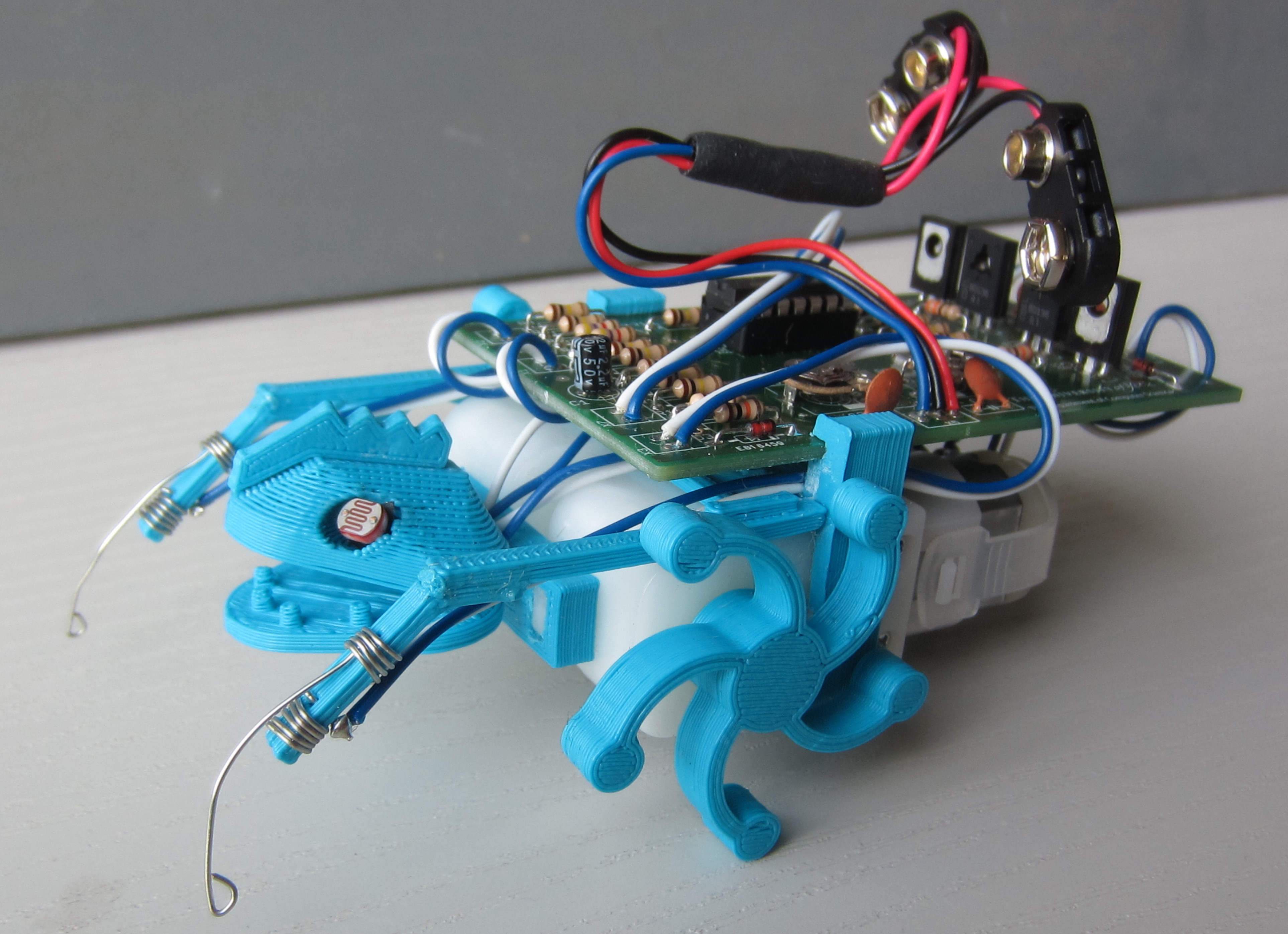
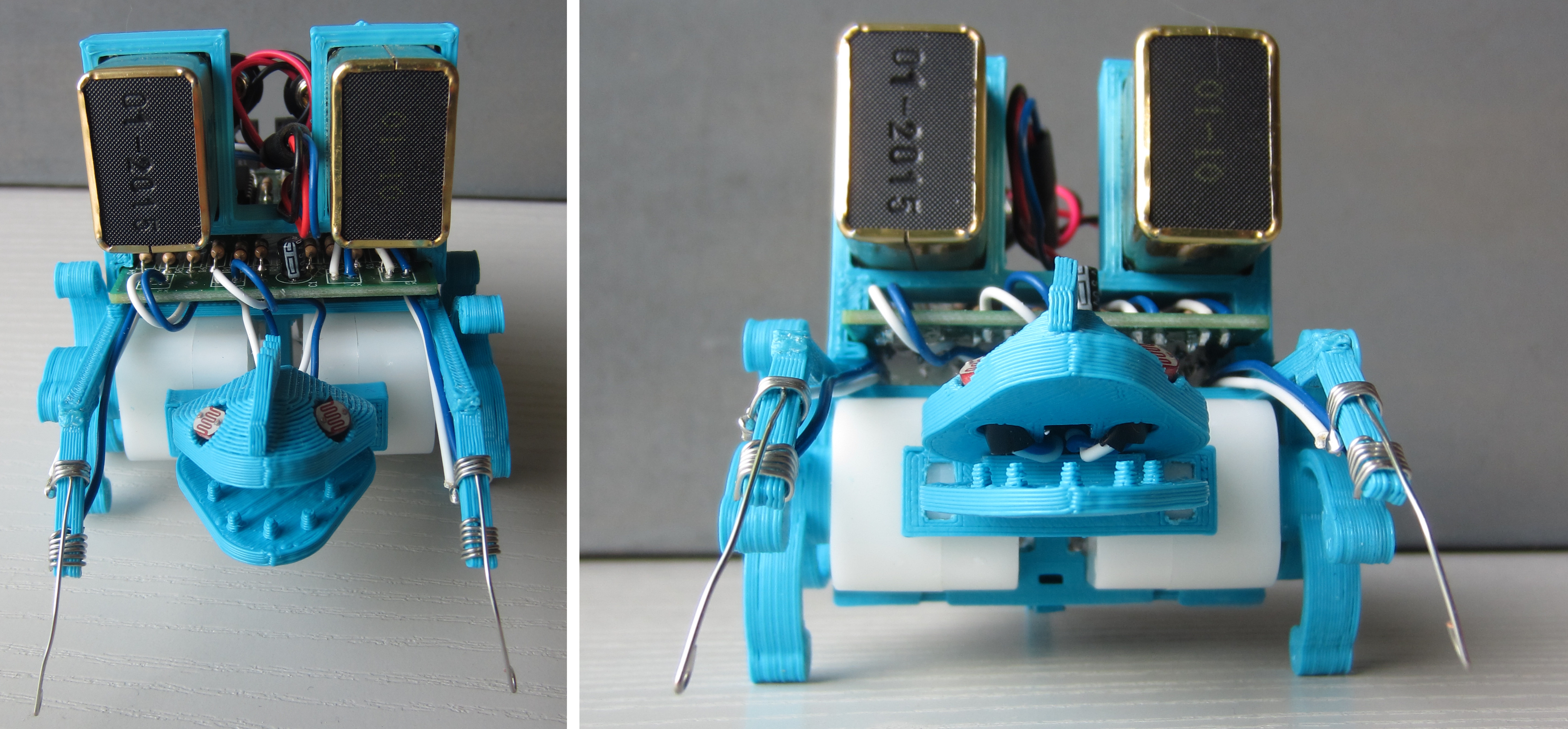
Figure 51 : PCB Zergling
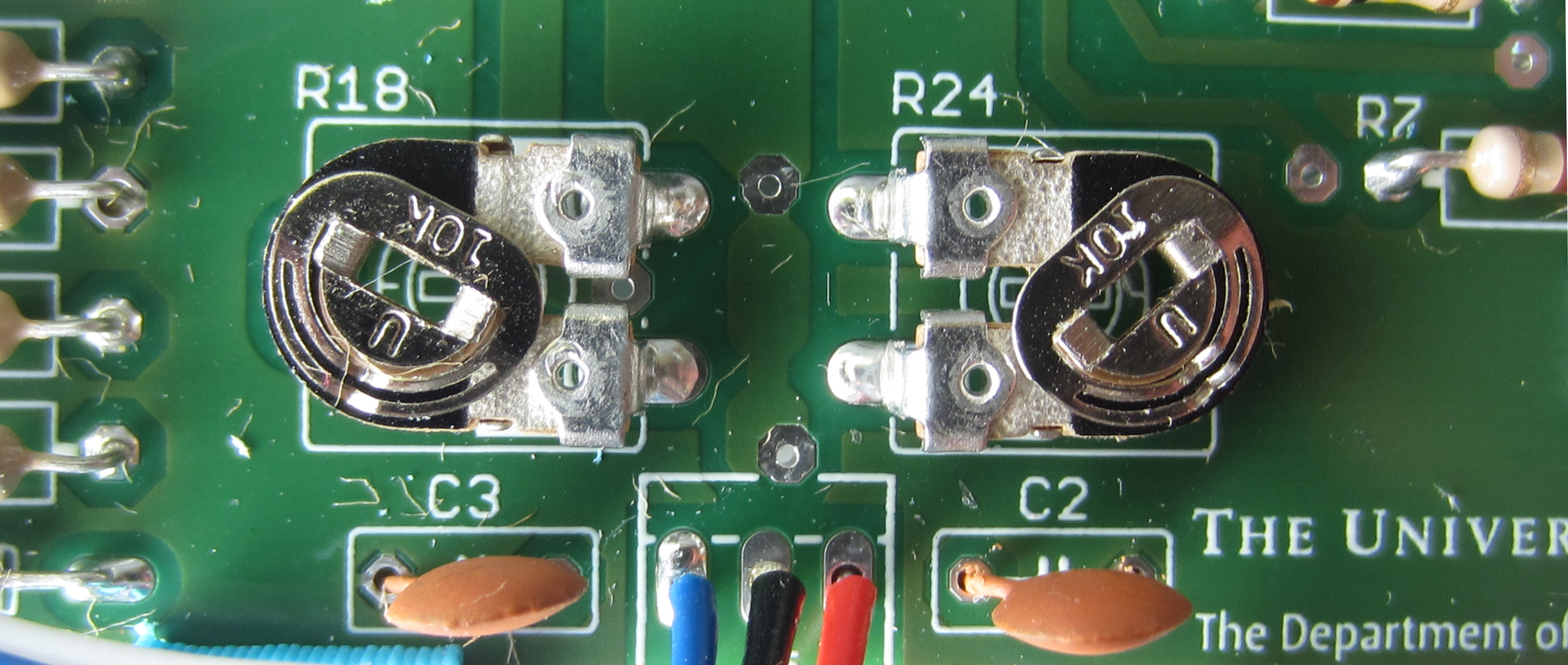
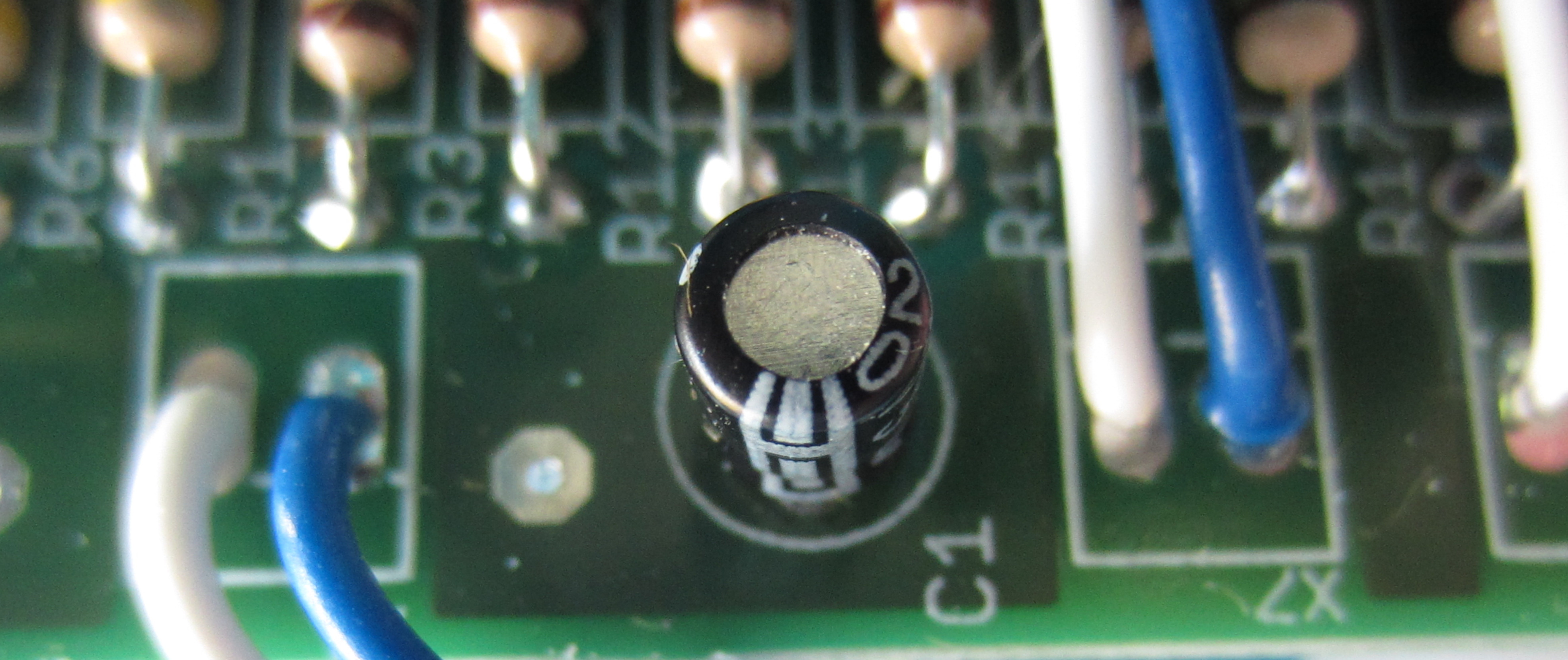

Figure 52 : Pot settings (top) and Capacitor (bottom)
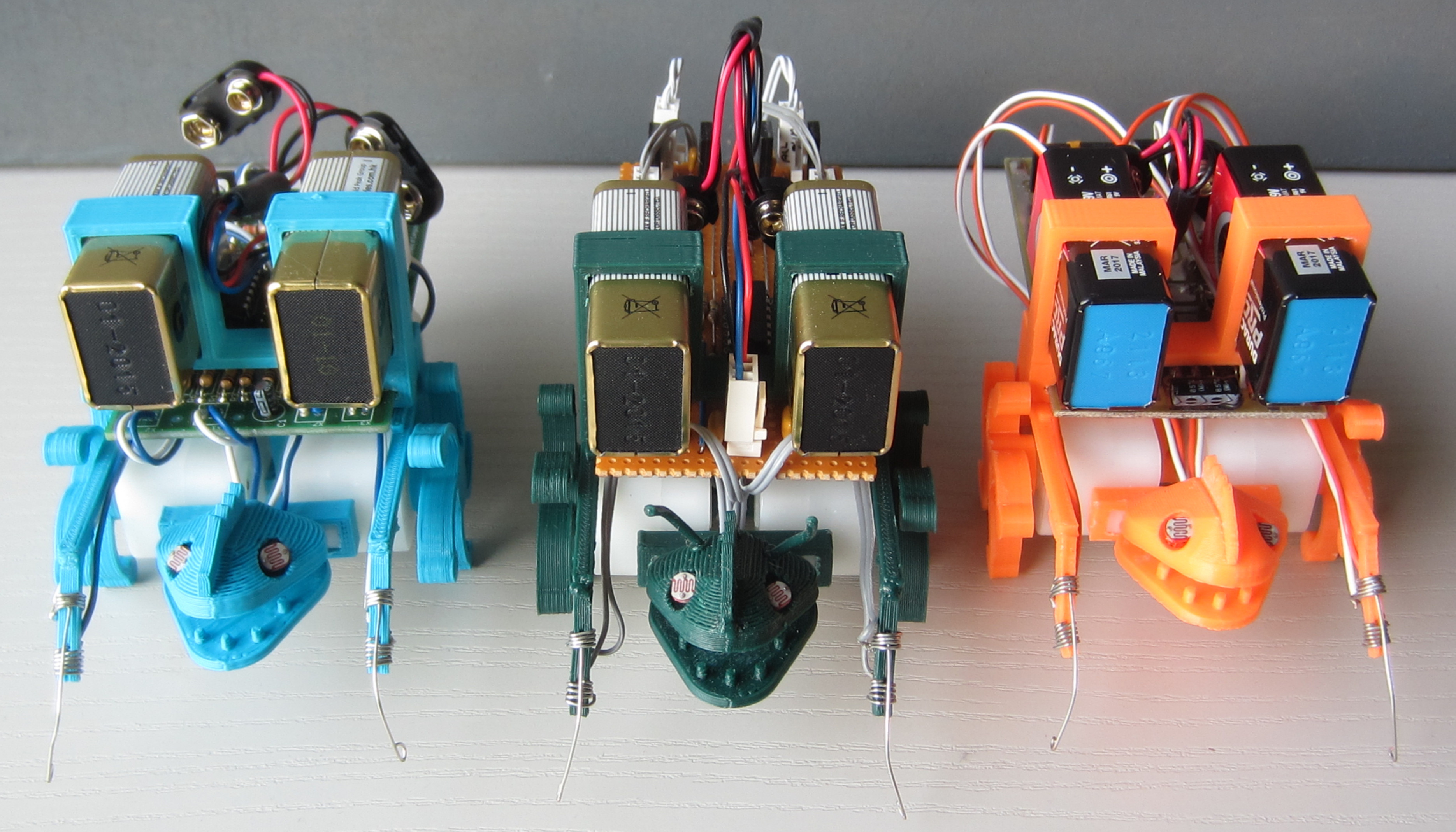
Figure 53 : the Zergling family
A change of plans, talking to David decided to make a BBC micro:bit version of the robot. These micro-controller boards were given to every year 7 (11- and 12-year old) child in Britain starting from October 2015 (LINK). This micro-controller is based around the ARM Nordic nRF51822 with 16K RAM, 256K Flash. At its heart is an ARM Cortex-M0 processor coupled to an accelerometer, magnetometer, Bluetooth, USB, 25 LEDs and two programmable buttons. Adding this controller to the Zergling is easy as its edge connector externalises its SPI, I2C and UART interfaces. Designing a solution that can be built by school children in schools, thats a slightly more tricky problem. Currently the plan is to build two versions:
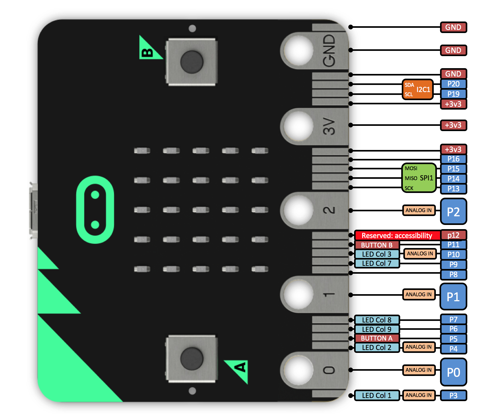
Figure 54 : BBC micro:bit
Another change of plans :). Decided that these changes are a fundamental mutation of the robot, a move from analogue neurons to a digital systems with software. Therefore, have decided that this new robot will evolve into a Roach (*** LINK ***), another Zerg creature from the Starcraft game. Therefore, for the moment further development of the Zergling is on hold.

This work is licensed under a Creative Commons Attribution-NonCommercial-NoDerivatives 4.0 International License.
Contact details: email - mike.freeman@york.ac.uk, telephone - 01904 32(5473)
Back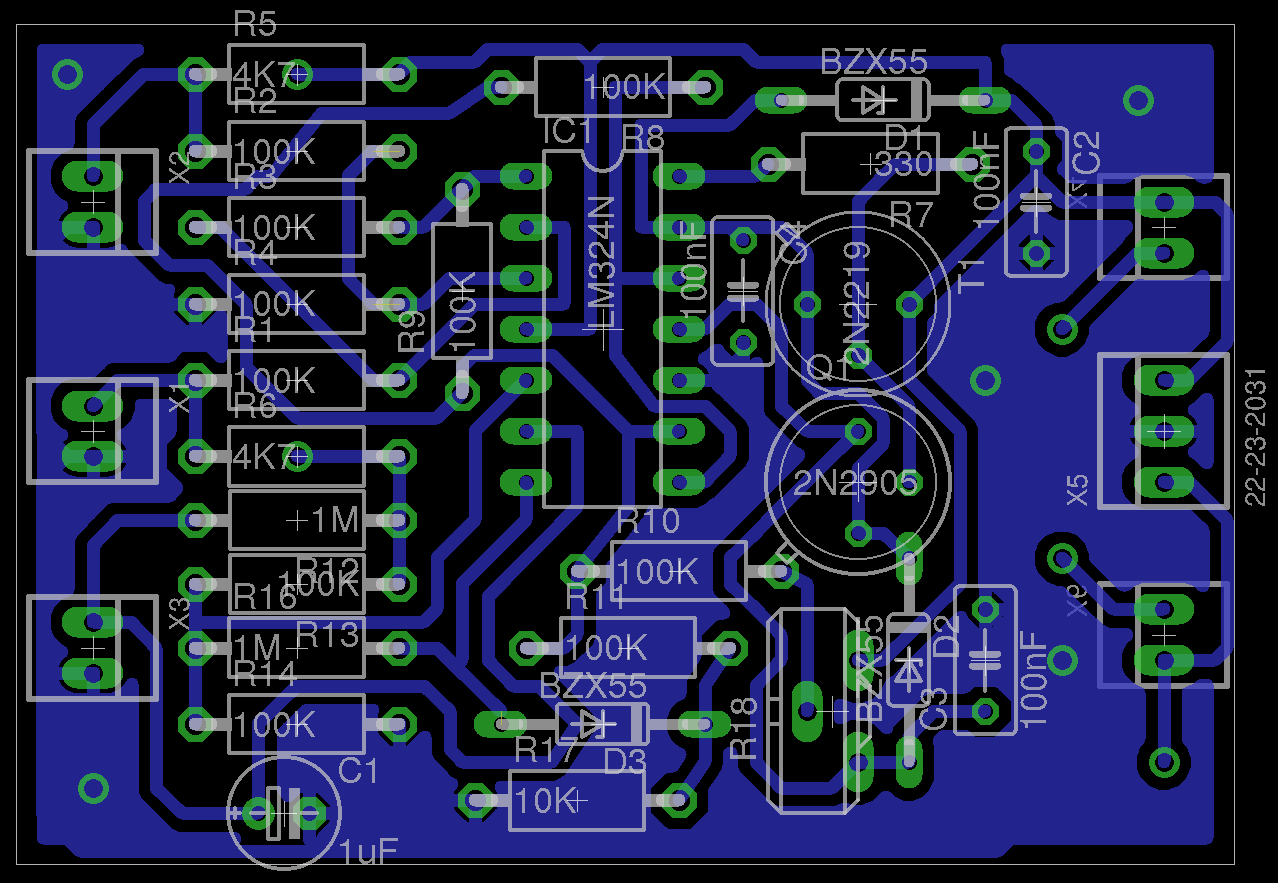