Never quite got around to finishing off these robots, all definitely work in progress, unfortuently, one day never seems to come. Updating this page (2018), i hope to finish of Ben, a classic 6502 based machine, the first processor i really programmed, has around 3000 lines of hand written assembler last time i looked, with my normal level of commenting :(.
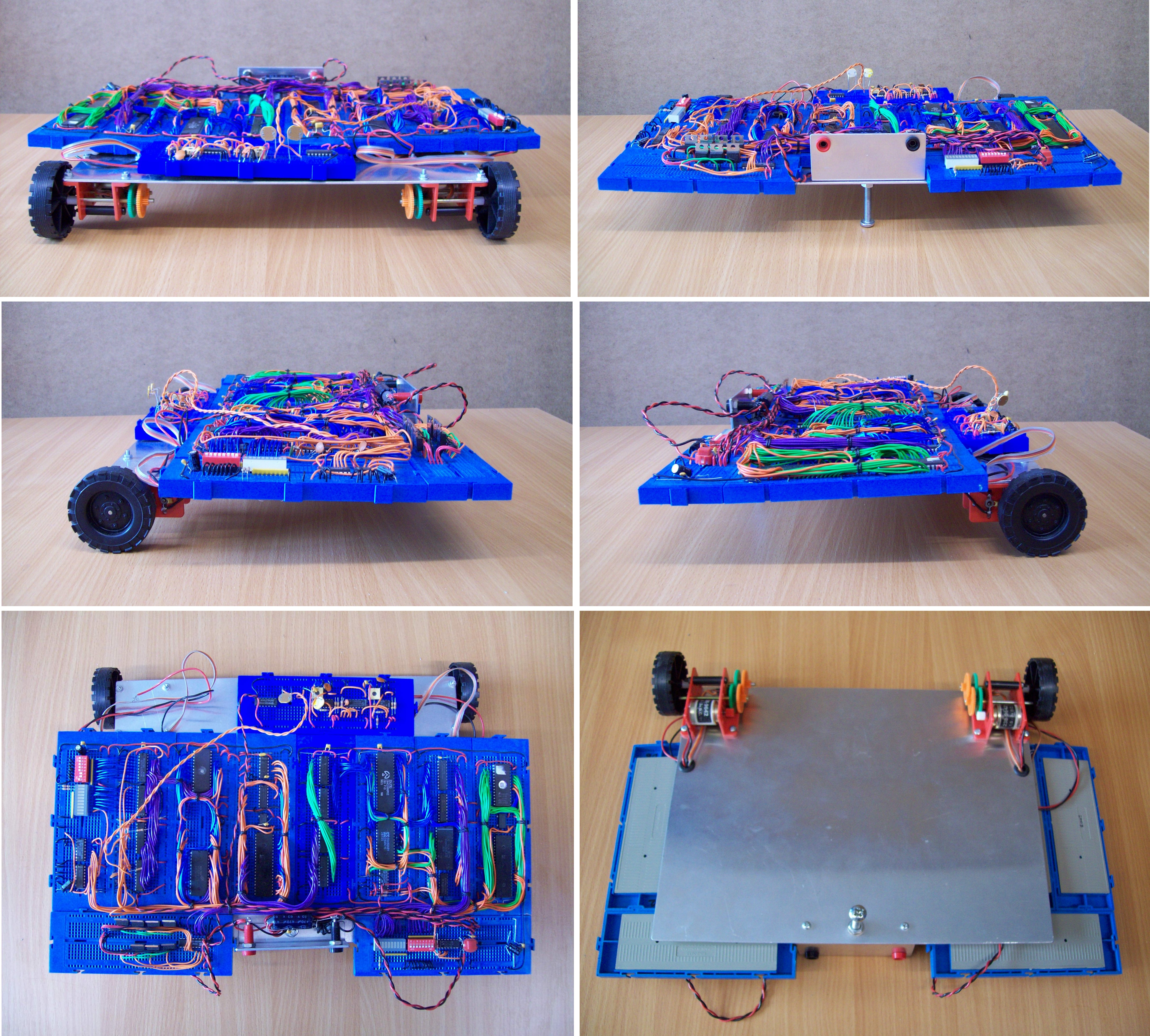
Figure 1.1 : BOT - front, back, sides, top and bottom
BOT: a simple bread board robot based around a Z80, CTC, PIO and TTL logic ICs. Built as a demonstrator when I taught the CTS module (student hardware group project). A nice platform for testing out speed control software, however, as it grow suffered from power supply issues, made it a little unreliable. Uses a H bridge for motor control with feedback from infra-red sensors mounted on each gearbox, giving approximately 256 pulses per revolution. Equipped with two processors, one controlling sensors (speed and light) and actuators (drive motors), the other performing the high level control (navigation and behaviour etc) communication via shared memory. Note, haven't used BOT for many years, definitely not functional, but could not make myself kill him. Update:28-6-2018, finally disassembled BOT, had to be done, but kept one of his Z80 cores as a teaching example.
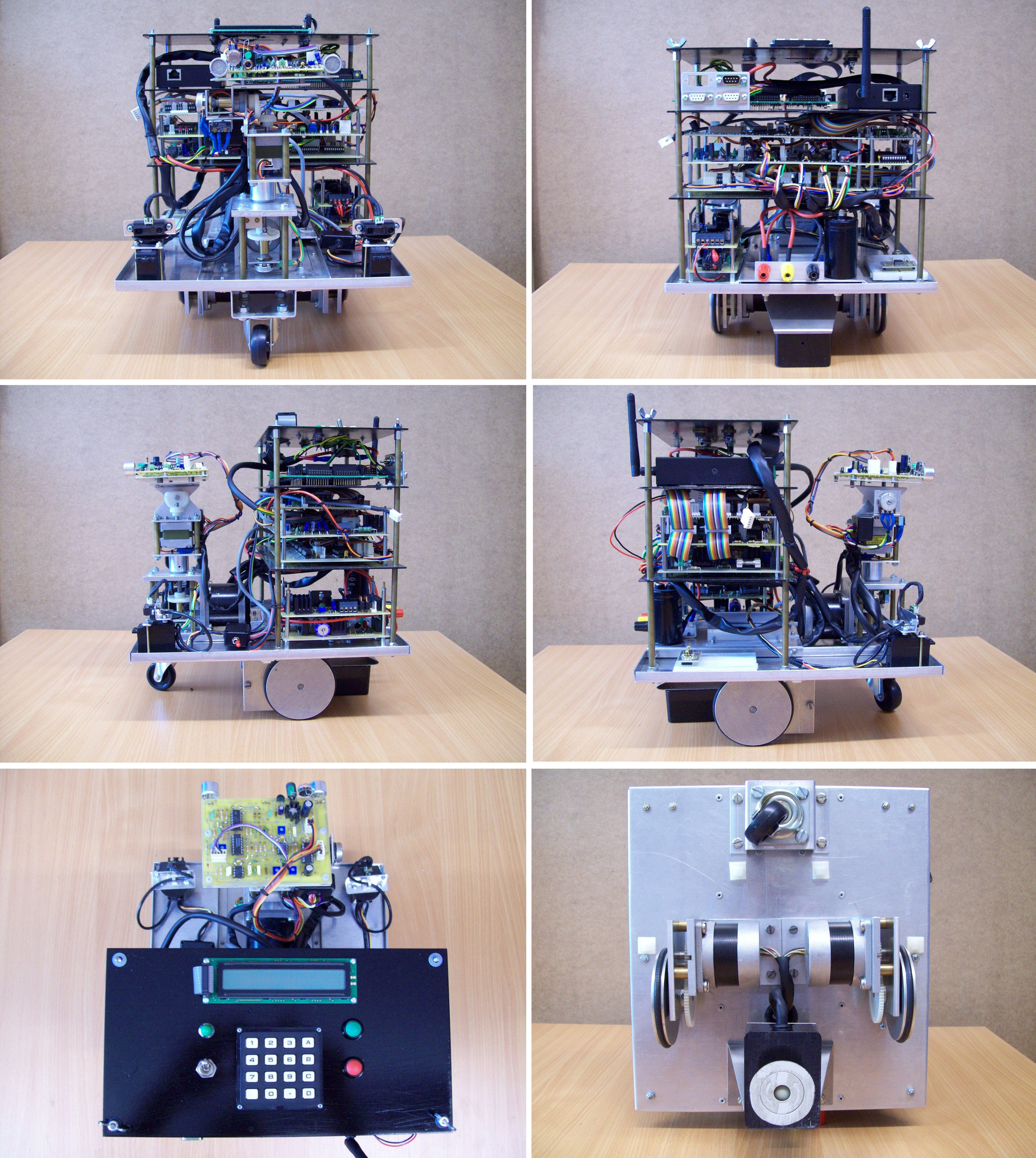
Figure 1.2 : BEN - front, back, sides, top and bottom
BEN: been working on this robot for a quite a long time, hasn't really been designed, but has rather evolved as new hardware was added. Based on a 6502 processor for low level motor / sensor control, supported with SPLD and FPGA hardware. Do confess I have a soft spot for the 6502 as it was the first processor I really used. As a result I do have a blind spot regarding all of its failings (especially the 8bit stack pointer). The 6502 used is a modern equivalent clocking at 4MHz (can go to 10MHz but I'm not convinced the PCB/cabling is up to it). It may be long in the tooth but it does give reasonable performance, if you ignore size, cost and power :). To improve performance a little more added two FPGA co-processors: IO and Maths, implemented in extremely old Xilinx XC4005 FPGAs (owing to their 5V tolerant IO) configured by VHDL/Schematic descriptions. The Maths co-processor has a 32 bit fixed point multiplier, adder, subtractor and comparator. The IO co-processor controls the infra-red distance sensor servo motors (mounted at the front of the robot), a serial mouse used to measure distance travelled (mounted on the bottom), the ultrasonic ranger finder and a high speed serial link to the main processor board. A simplified block diagram is shown in figure 1.2.1. Ideally the co-processors would be on the processor's local bus, however, due to cabling and space constraints (lack of connectors) I had to place these components on the expansion bus. This incurs a significant reduction in bandwidth, will rewire at some point.
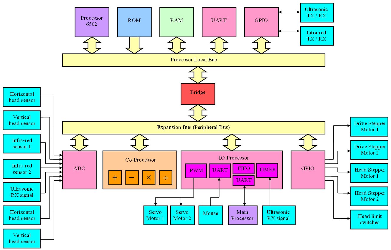
Figure 1.2.1 : Low level architecture block diagram (not ideal)
Simple GPIO + MOSFET drives are used to control the main drive stepper motors (differential steering) and the horizontal and vertical head stepper motors. The 6502 generates the required motor phase signals implementing full and half stepping modes. The infra-red communications link (mounted on head) is also bit-bashed through GPIO allowing the robot to locate and interrogate active beacons in its environment i.e. robot TX wakeup code, if beacon in range it responds with its ID code. The IO-processor also implements the high speed comms link to the main processor board, buffered through a hardware FIFO and a circular buffer in 6502 RAM. The main processor board contains two processors, a 68332 micro-controller and a Xilinx MicroBlaze implemented in a Virtex II FPGA, as shown in figure 1.2.2.
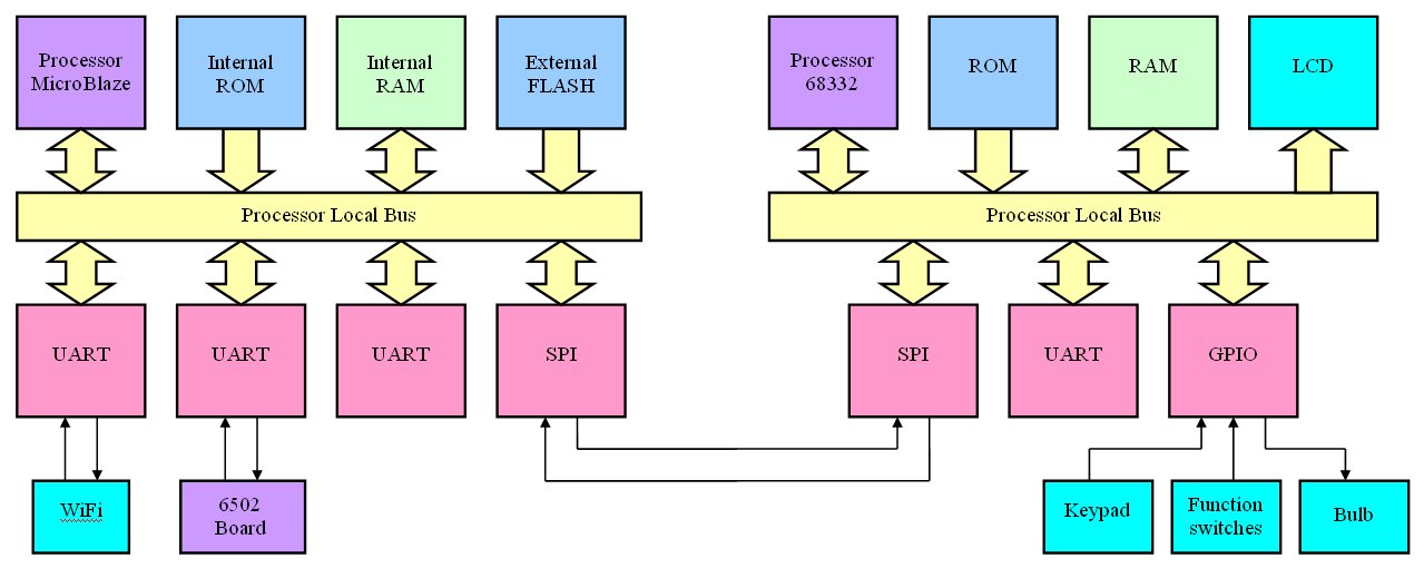
Figure 1.2.2 : Top level architecture block diagram
The top level processors implement the robot's control and communications functionality. The 68332 has at its core the CPU32 processing module derived from the 68020 processor. This communicates with the MicroBlaze processor across a high speed SPI serial link allowing functionality to be distributed between these processing elements e.g. navigation, localization, signal data processing etc. These processors and the serial to Wifi adaptor are currently being rewired i.e. the top platform in figure 1.2. At present this robot is used in a student project looking at how ultrasonic data combined with binary neural networks can be used to localize a robot within a map. The final aim of this work is implement this functionality in a binary neural network co-processor (an existing VHDL IP-core) implemented on the Virtex II FPGA.
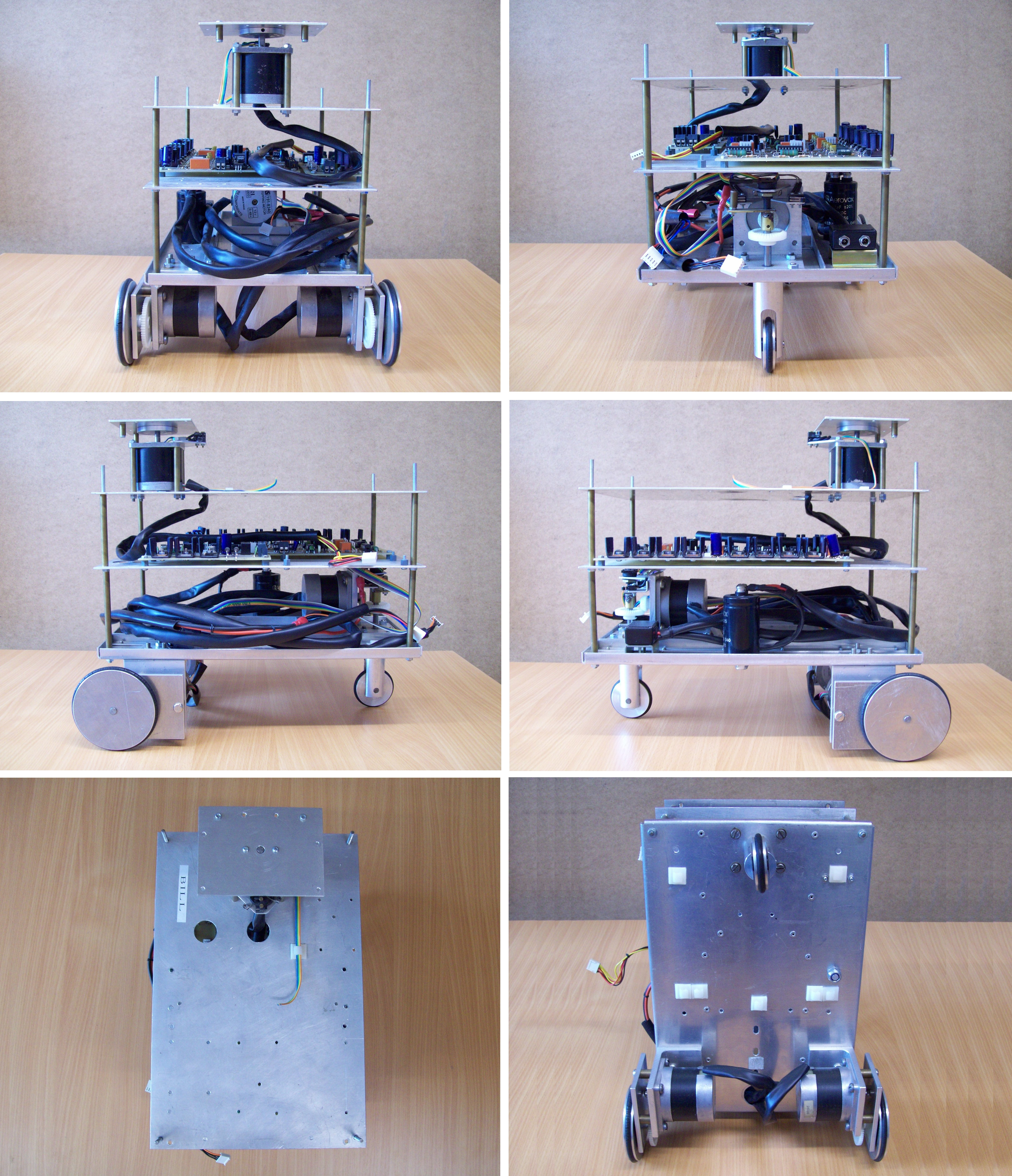
Figure 1.3 : BIL - front, back, sides, top and bottom
BIL: BIL(L) the second half of the team. However, as you can see from the photos BIL isn't feeling very well at the moment :). Currently going through a refit, replacing the ultrasonic range finder with a stereo camera system based around a pair of Kodak KAC-9628 CMOS image sensors. These will be interfaced to a Xilinx Virtex II, or Xilinx Spartan 3 FPGA, however, need to design a PCB for the frame buffer memory. Its surprising how much memory a robot needs when you start to process image data i.e. many mega-bytes, owing to the camera's VGA resolution. Definitely a work in progress. The envisaged architectural block diagram is shown in figure 1.3.1. This robot again uses stepper motors as its main drive motors. The drive circuit is a little different from BEN's, uses 5V stepper motors operated from a 12V supply with current limiting. This reduces the coil voltage rise time, giving more drive power resulting in significantly higher top speeds. This robot can be operated using differential drive steering, but can also be reconfigured to use rear/front steering via a fixed wheel, this being rotated by an additional stepper motor (in differential mode rear fixed wheel replace with a caster wheel). The aim of this work is to use the stereo image data combined with a binary neural network to localize the robot's position within a map. Again, it is intended that the final system will be implement in a binary neural network co-processor (an existing VHDL IP-core) implemented on the Virtex II FPGA.
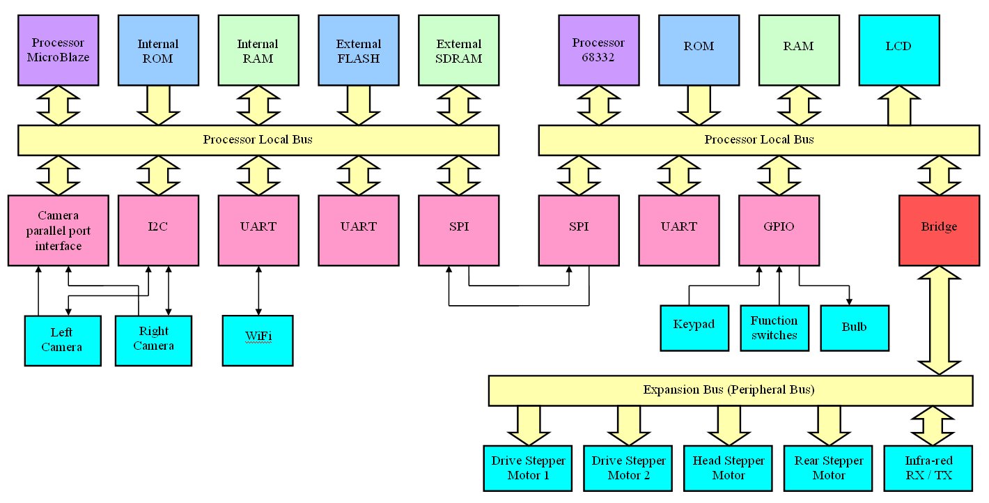
Figure 1.3.1 : Top level architecture block diagram
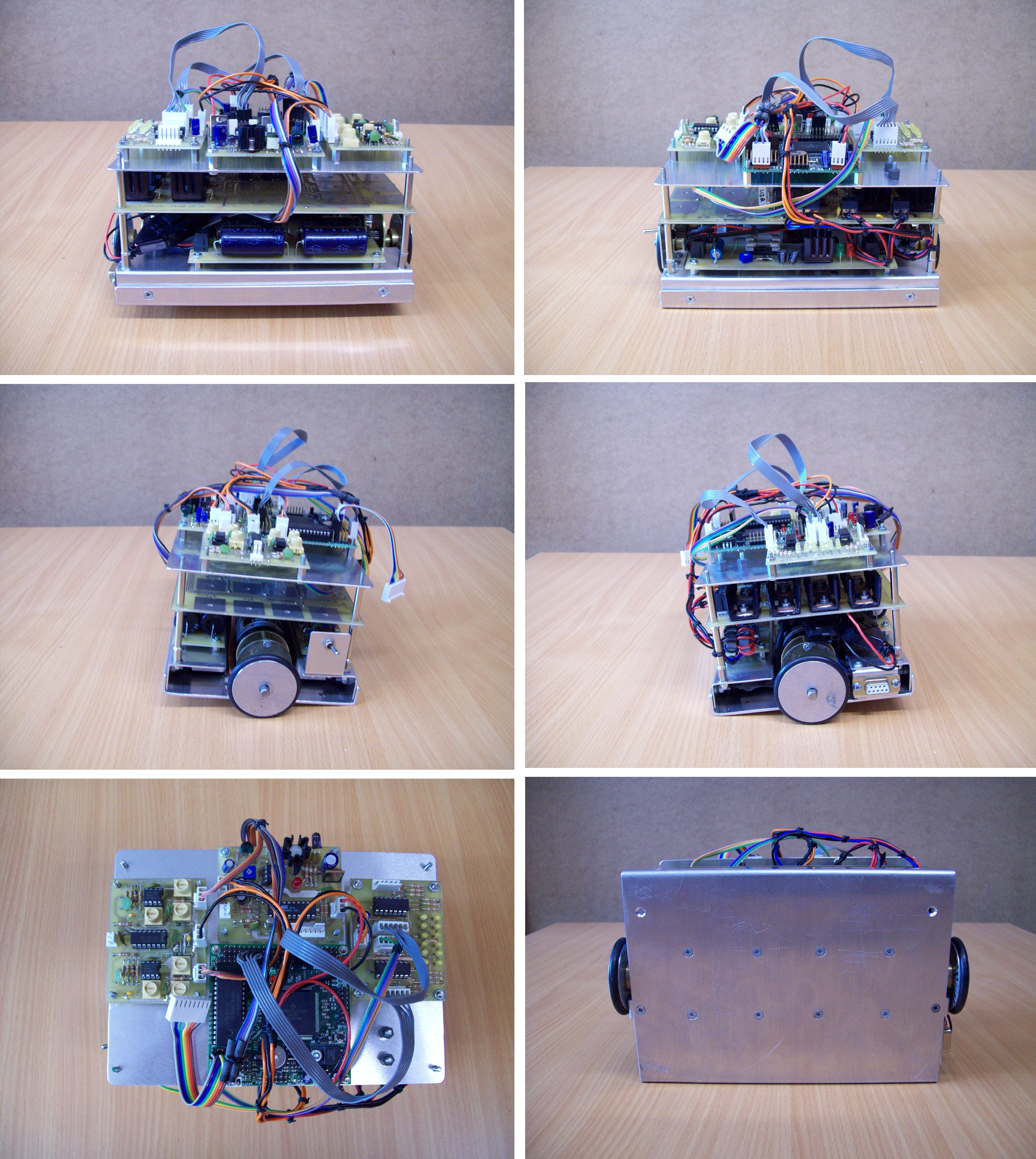
Figure 1.4 : BUD - front, back, sides, top and bottom
BUD: original designed as a prototype buggy for a robocup football team, however, now used as a test platform for high speed robot control. Unlike the previous robots the main drive motors are DC motors with a 11:1 reduction gear box. For the size and weight of this robot these motors are considerably over spec'ed allowing the robot to achieve quite impressive rates of acceleration and top speeds (measured by the depth of the indentation left when it crashes into a wall). Architecturally a relatively simple architecture based on a 68332 micro-controller, interfacing to both gyroscope and accelerometer sensors through its SPI serial interface. Motor control is implemented using a standard H bridge controller (MOSFET) and PWM. In addition to the gyroscope and accelerometer each wheel has a simple wheel encoder. The encoder disks are printed onto transparencies and glued onto each wheel as shown in figure 1.4.1. These are read by an infra-red sensor i.e. measuring and thresholding the reflected light from the clear and black segments, giving either 4, 8, or 16 pulses per revolution, very low resolution, but its better than nothing (and it cheap :).
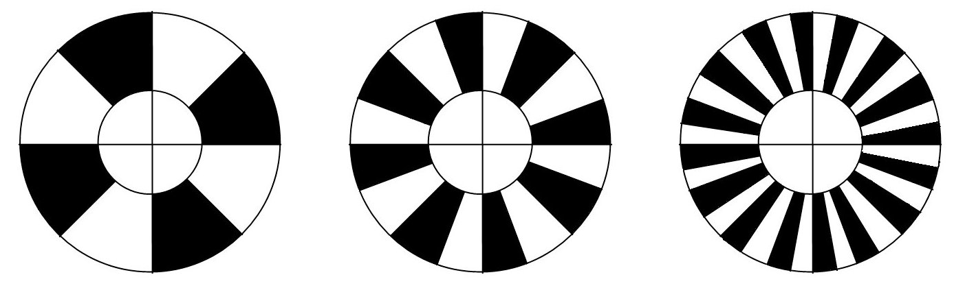
Figure 1.4.1 : Wheel encoders
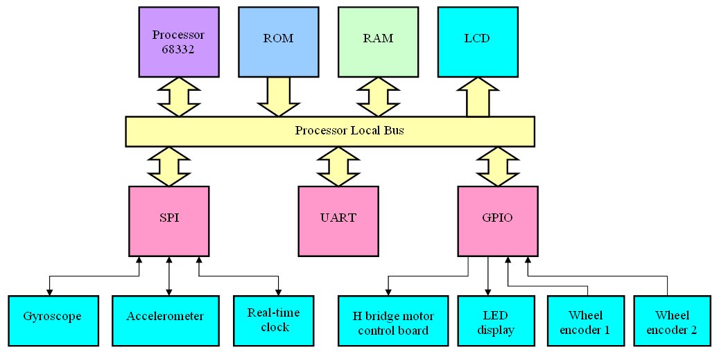
Figure 1.4.2 : Top level architecture block diagram
To minimize the amount of damage to the departments skirting boards BUD's control algorithms can be tested on a simple rolling road, as shown in figure 1.4.2. This allows one drive motor to be monitored using a high resolution encoder as it drives/accelerates a known mass. This data is logged by another 6502 board (data logger) allowing the user to download this data (iHex format) after each test run. In addition to this known load a variable load can be applied to the drive motor using a 'load' motor. This is coupled to the mass using a friction drive wheel, pulled into position by a solenoid during a test run. The voltage applied to this motor is again controlled by the data logger (6502) through a DAC, allowing previously uploaded load curves (iHex files) to be applied during a test run e.g. to simulate a inclines, variations in terrain, rough/smooth surfaces etc. At present this robot is used in a student project looking at how sensor data can be combined to control/enhance the robots manoeuvring abilities at high speeds.
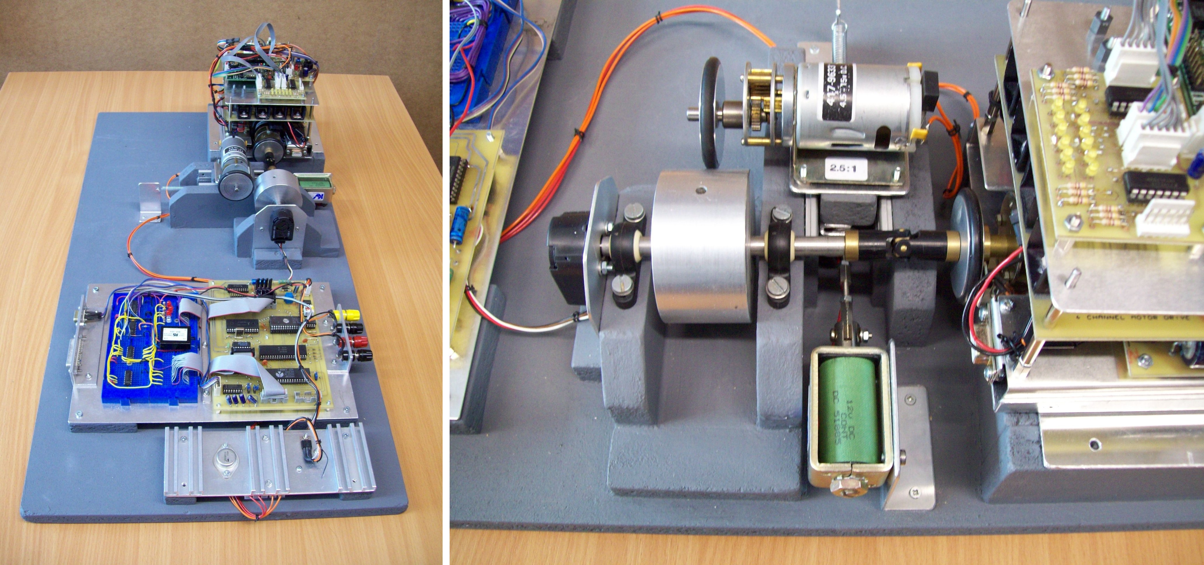
Figure 1.4.2 : Rolling road
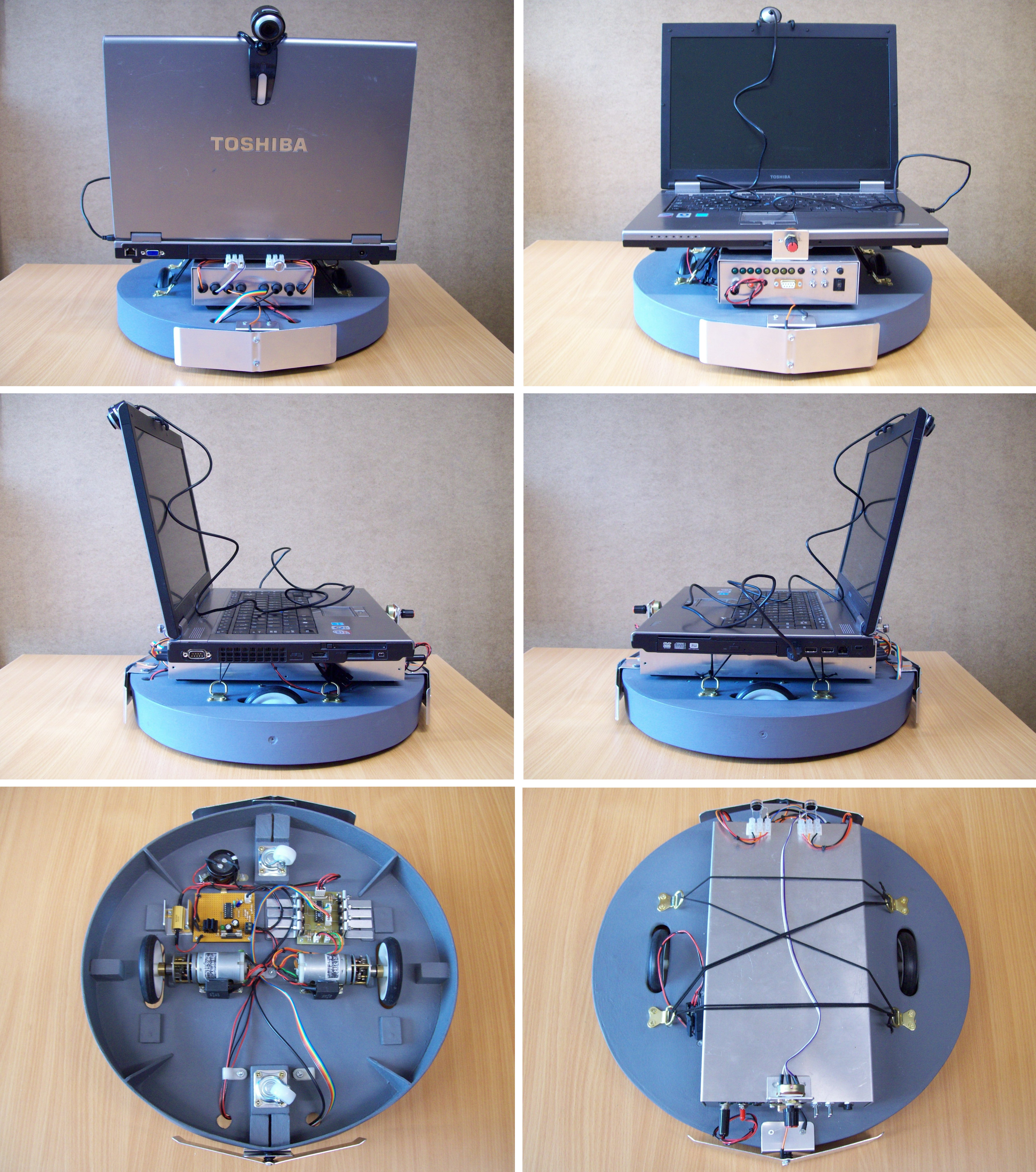
Figure 1.5 : BOD - front, back, sides, top and bottom
BOD: this robot is a general purpose mobile platform constructed to temporarily replace BIL. The intention is to evaluate and implement the vision processing algorithms required in BIL on a standard laptop PC with a webcam. To manoeuvre this platform two DC motors with a 50:1 reduction gear box are used (due to its increased weight), controlled using a standard H bridge controller (MOSFET) and PWM. The main navigation , obstacle detection, course correction algorithms are implemented on the laptop PC using camera image data, therefore, the platform has minimal number of additional sensors: left/right light sensors and front/rear bump sensors. There is space for four addition bump sensors i.e. front left/right and rear left/right, which will be added later. These actuators and sensors are controlled by another 6502 base control board which is connected to the laptop PC via a RS232 serial link. This communication link allows the PC to request sensor data and send movement commands e.g. move forwards 50cms, turn left 90 degrees etc. These commands are buffered in the 6502's local RAM and are issued as each command completes. At present this robot is used in a student project looking at how camera data combined with binary neural networks can be used to localize a robot within a map. The final aim of this work is implement this functionality in a binary neural network co-processor (an existing VHDL IP-core) implemented on the Virtex II FPGA.
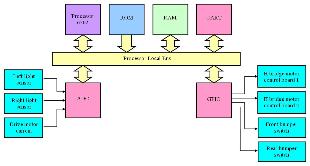
Figure 1.5.1 Top level architecture block diagram
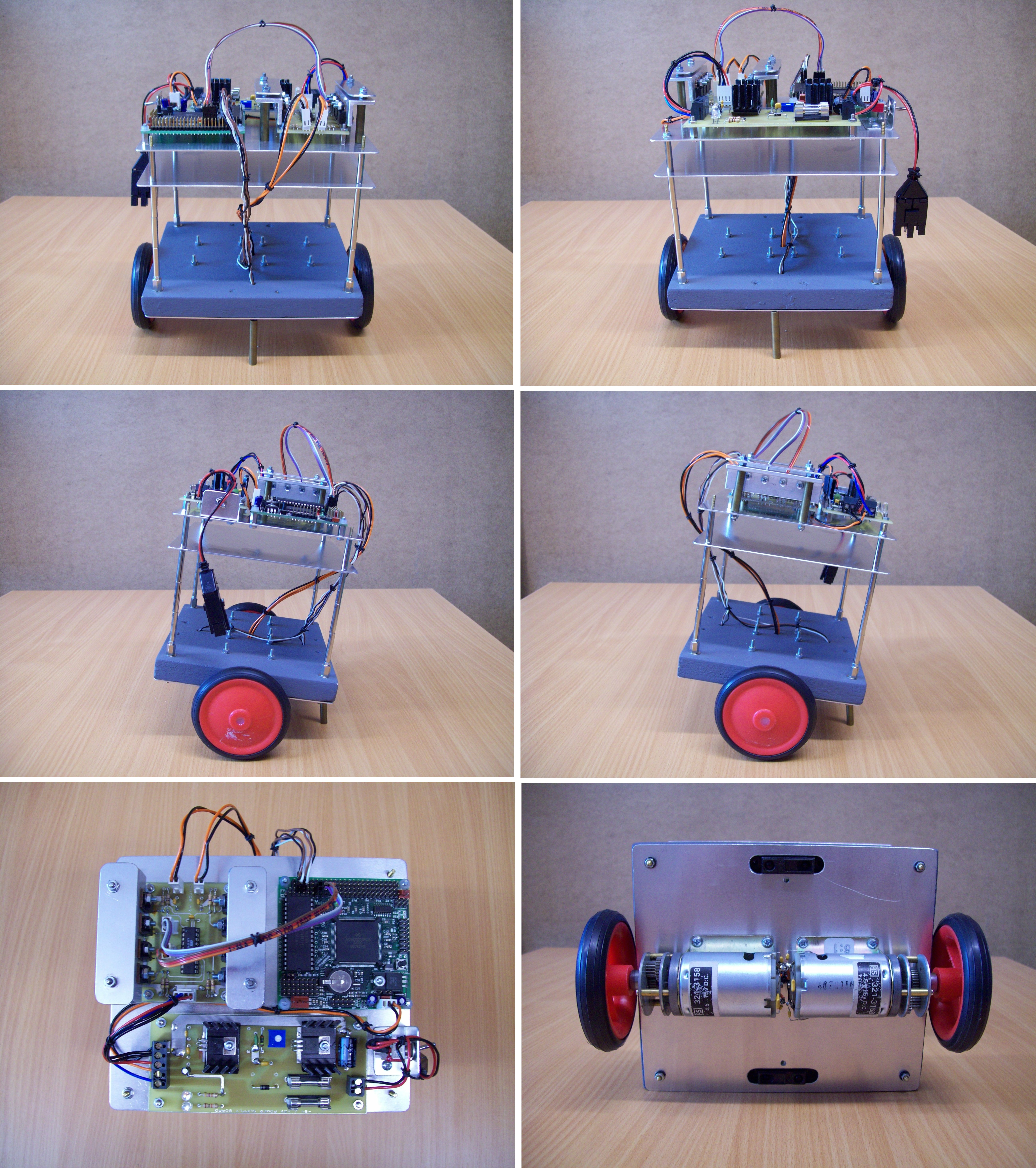
Figure 1.6 : BAL - front, back, sides, top and bottom
BAL: always wanted to make a balancing robot i.e. a Segway Bot. Currently in the process of making a test platform using the two infra-red range sensors mounted front and back. The intention is to use the difference of these sensor signals as the error signal to a PID controller, allowing the robot to balance without the need of the brass stand-off shown in the photos. Hope to also use the gyroscope and accelerometers used by BUD, definitely a work in process. Hope to get a prototype working by the end of the year (work allowing).