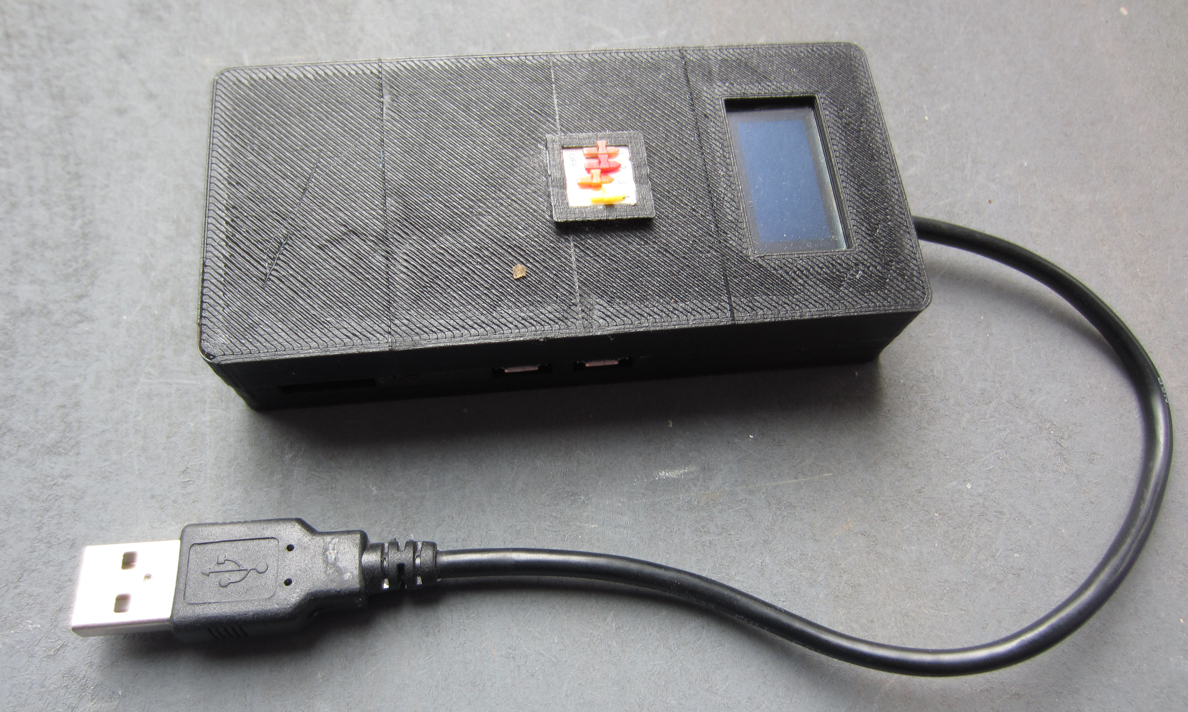
Figure 1 : BadPi
Inspired by the Hak5 rubber ducky LINK and bad-usb devices made from Arduinos LINK decided to build one for fun from a Pi zero W. These devices emulate human-input-devices (hid) such as keyboards, mice and joysticks. They can also emulate network device i.e. ethernet-over-USB, allowing you to create SSH bridges using the Wifi interface. There are Pi images out there for such devices, but being a 'trusting' soul wanted to build one from source. Also, in addition to this functionality also wanted to add some input / output interfaces on the BadPi, to allow you to set its operating mode and functions once plugged into a target machine. This does increase its size, as shown in figure 1, no longer has the appearance of a USB pen-drive, more of an external USB hard disk, or MP3 player. Below is an outline of the work so far, some success, but not finished yet, still work to be done.
Basic Hardware / Software
UART, RNDIS & ECM
USB disk
Ducky scripts
Wifi bridge
Wifi sniffer
Ethernet sniffer
The first challenge was to get the USB hid emulation work. Googling around found this web page LINK, initially no joy. Further reading found that the kernel had been updated since this tutorial was written, so the methods described do not work on the latest versions of Raspian. Solution, roll back to a previous version LINK, to cut a long story short, downloaded a lot of older versions and found that 2017-02-16-raspbian-jessie worked ok for me (do confess lost count, but it was around that version). To check you have the right kernel version as me run uname:
uname -a
Linux raspberrypi 4.4.50+ #970 Mon Feb 20 19:12:50 GMT 2017 armv6l GNU/Linux
As shown, for me this returns version 4.4.50. At its core my implementation follows this tutorial, a few modifications as i wanted to be able to select what 'gadgets' were enabled on boot using dip switches. Basic install is as follows. Add to the end of /boot/config.txt:
dtoverlay=dwc2
Next add to the end of /etc/modules, loads the required modules at boot, also enables the I2C interface that is used to control the display:
i2c-dev
dwc2
libcomposite
Note, small problem i found that when these modules are enabled i had problems trying to get the local keyboard to work, not surprising if the Pi is emulating a keyboard. Not a big issue as normally running the Pi headless and SSHing. Therefore, make sure you have setup the Wifi interface before you reboot, otherwise you won't be able to access the Pi. Later, can also open a terminal over serial and Ethernet-over-USB i.e. a peer-to-peer connection.
To allow the Pi to be powered and communicate over a normal USB cable, you need to solder on an old USB cable. Cut and strip a USB cable with a male USB A connector (shown in figure 1), this will expose 5 cables:
Solder these wires to the corresponding coloured pads shown in figure 2, the trick here is to tin these wires first, then trim back the wire to a short stub, this helps prevent the insulation shrinking further when you solder them to the pad i.e. helps ensure the wire does not bridge a track on the pcb. Heat shrink or tape the screen cable so that it does not touch the pcb.
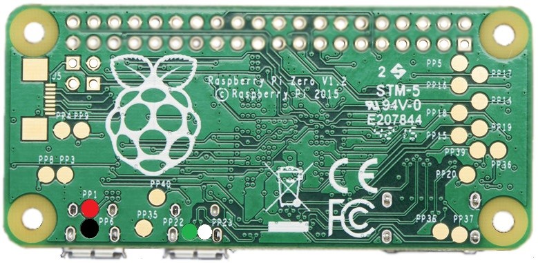
Figure 2 : Pi USB solder pads
Rather than running a script from rc.local as suggested in the original tutorial i set a sudo cron job to run at boot, at the command line type: sudo crontab -e then enter:
@reboot date >> /home/pi/bin/error
@reboot date >> /home/pi/bin/log
@reboot /home/pi/bin/go.sh 1>>/home/pi/bin/log 2>>/home/pi/bin/error
The script go.sh is shown below. This script changes directory to ~/bin so that any files produced go into this directory, it then reads the dip switches connected to GPIO lines, shown in figure 3, writing their state to the file mode. The DIP switches do not need any external circuitry, using internal pull-ups. As they are only read on boot switch bounce is also not an issue.
#!/bin/sh
#go.sh - start script
cd /home/pi/bin
sudo /usr/bin/python /home/pi/bin/dipSwitches.py
sudo /home/pi/bin/startBoot.sh
sleep 0.5
sudo /home/pi/bin/startBadUsb.sh
sleep 0.5
sudo /usr/bin/python /home/pi/bin/displayButtons.py
The code for dipSwitches.py is below, reads GPIO lines and sets associated bit in variable value before writting this data to the file mode.
#dipSwitches.py
import RPi.GPIO as GPIO
import time

GPIO.setwarnings(False)
GPIO.setmode(GPIO.BCM)

# Inputs: 18, 23, 24, 25

GPIO.setup(18, GPIO.IN, pull_up_down=GPIO.PUD_UP)
GPIO.setup(23, GPIO.IN, pull_up_down=GPIO.PUD_UP)
GPIO.setup(24, GPIO.IN, pull_up_down=GPIO.PUD_UP)
GPIO.setup(25, GPIO.IN, pull_up_down=GPIO.PUD_UP)

value = 0
if (GPIO.input(18)==1):
        value = value | 8

if (GPIO.input(23)==1):
        value = value | 4
if (GPIO.input(24)==1):
        value = value | 2
if (GPIO.input(25)==1):
        value = value | 1

print value

f = open("mode", "w")
f.write(str(value))
f.close()
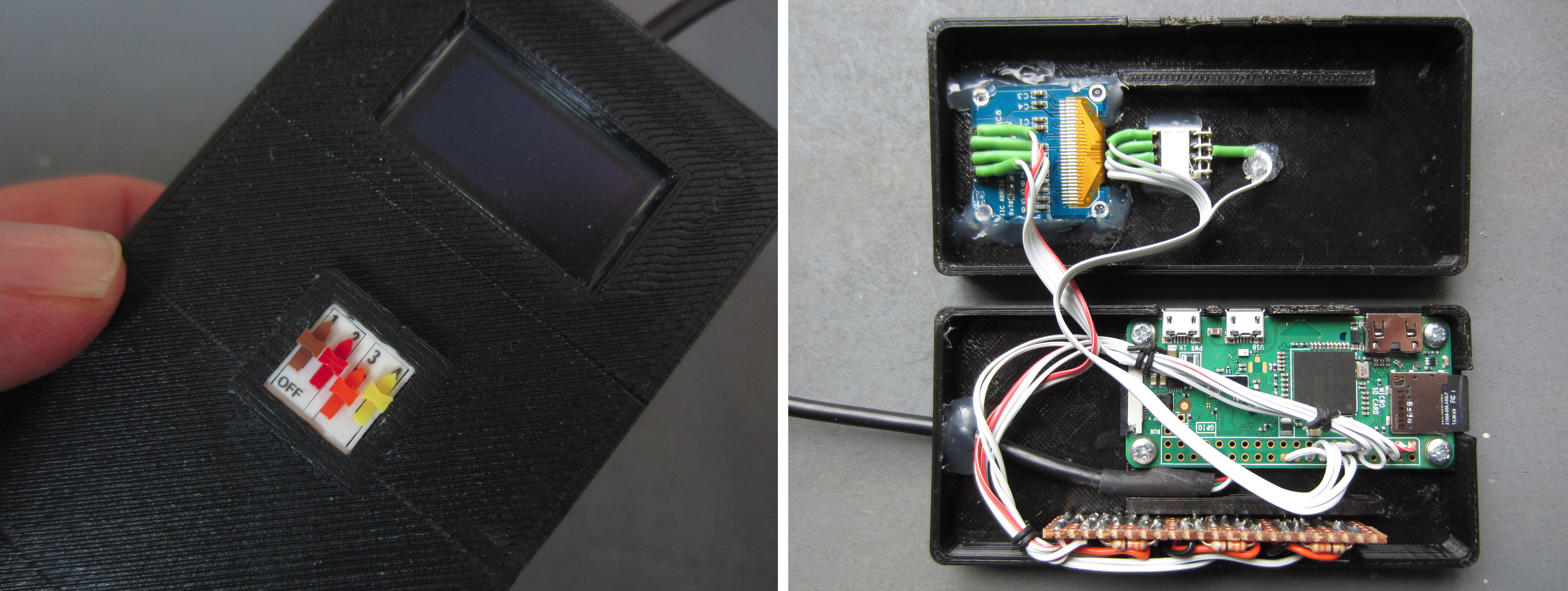
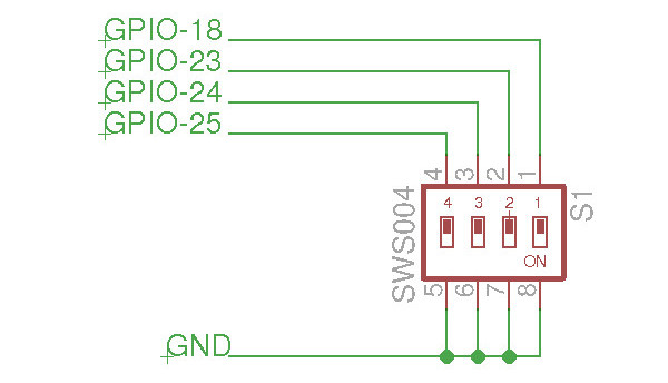
Figure 3 : DIP switches
The script startBoot.sh is then executed, not really needed, this writes to the display status/debug information, allowing the user to see what mode the Pi is booting into, useful for a headless box.
#!/bin/sh
# startBoot.sh - display debug/status info

if test -e mode
then
        mode=`cat mode`
        if test $mode -eq 1
        then
                #keyboard + serial
                echo badUsbMode1
                /usr/bin/python /home/pi/bin/bootMessage.py 1
        else
                if test $mode -eq 2
                then
                        #keyboard + serial + disk
                        echo badUsbMode2
                        /usr/bin/python /home/pi/bin/bootMessage.py 2
                else
                        if test $mode -eq 3
                        then
                                #keyboard + serial + disk + ethernet
                                echo badUsbMode3
                                /usr/bin/python /home/pi/bin/bootMessage.py 3
                        else
                                echo baseRaspberryPi
                        fi
                fi
        fi
fi
The display shown in figure 4 is a OLED 128x64 display, controlled using bootMessage.py below. This is based on the Adafruit libs LINK, just works out of the box, as always Adafruit has very good software and support. Note, the display is powered from the +3V & 0V supply from the GPIO header. SDA and SCL are also just wired to the header, no external pull-up resistors used.
# bootMessage.py

import Adafruit_SSD1306
import time

from PIL import Image
from PIL import ImageFont
from PIL import ImageDraw

import sys


def menu():
    global payloads
    print sys.argv[0], sys.argv[1]

    # Draw a black filled box to clear the image.
    draw.rectangle((0,0,width,height), outline=0, fill=0)

    if(sys.argv[1] == '0'):
        size = 9
        offset = 1
        draw.text((left, top),                 "Booting ...",  font=font, fill=255)
        draw.text((left, top+(size*1)+offset), "  PiZero", font=font, fill=255)

    elif(sys.argv[1] == '1'):
        size = 9
        offset = 1
        draw.text((left, top),                 "Booting ...",  font=font, fill=255)
        draw.text((left, top+(size*1)+offset), "  Keyboard", font=font, fill=255)
        draw.text((left, top+(size*2)+offset), "  Serial", font=font, fill=255)

    elif(sys.argv[1] == '2'):
        size = 9
        offset = 1
        draw.text((left, top),                 "Booting ...",  font=font, fill=255)
        draw.text((left, top+(size*1)+offset), "  Keyboard", font=font, fill=255)
        draw.text((left, top+(size*2)+offset), "  Serial", font=font, fill=255)
        draw.text((left, top+(size*3)+offset), "  Disk", font=font, fill=255)

    elif(sys.argv[1] == '3'):
        size = 9
        offset = 1
        draw.text((left, top),                 "Booting ...",  font=font, fill=255)
        draw.text((left, top+(size*1)+offset), "  Keyboard", font=font, fill=255)
        draw.text((left, top+(size*2)+offset), "  Serial", font=font, fill=255)
        draw.text((left, top+(size*3)+offset), "  Disk", font=font, fill=255)
        draw.text((left, top+(size*4)+offset), "  Ethernet", font=font, fill=255)

    else:
        size = 9
        offset = 1
        draw.text((left, top),                 "Booting ...",  font=font, fill=255)
        draw.text((left, top+(size*1)+offset), "  Default", font=font, fill=255)


    # Display image.
    disp.image(image)
    disp.display()

RST = None     # on the PiOLED this pin isnt used
disp = Adafruit_SSD1306.SSD1306_128_64(rst=RST, i2c_address=0x3c)
disp.begin()

# Clear display.
disp.clear()
disp.display()

width = disp.width
height = disp.height

padding = 1
top = padding
bottom = height-padding
left = 1
right = 126

# Create blank image for drawing.
# Make sure to create image with mode '1' for 1-bit color.
image = Image.new('1', (width, height))

# Get drawing object to draw on image.
draw = ImageDraw.Draw(image)

# Load font.
font = ImageFont.load_default()
#font = ImageFont.truetype('Minecraft.ttf', 12)
#font = ImageFont.truetype('visitor1.ttf', 9)
#font = ImageFont.truetype('apple.ttf', 7)

menu()

time.sleep(0.5)
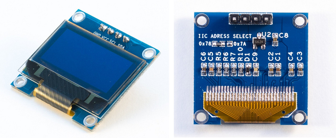
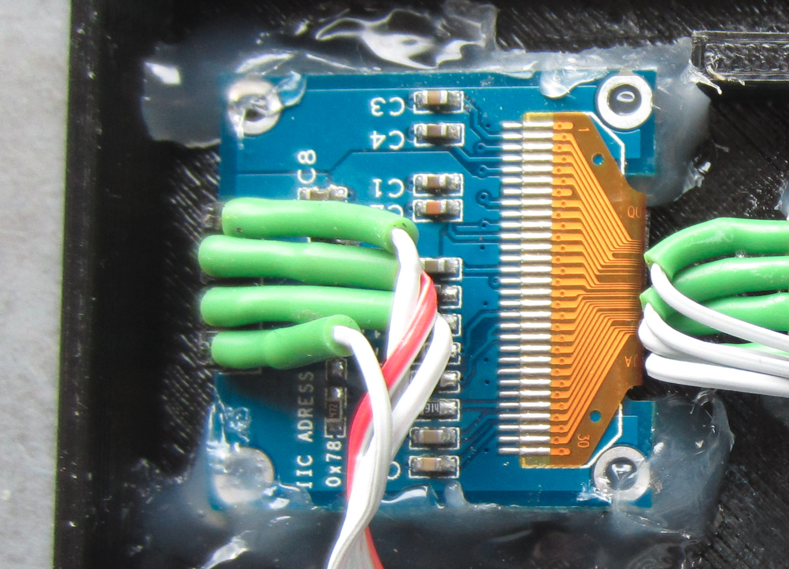
Figure 4 : Display
USB gadgets are started using startBoot.sh, shown below.
#!/bin/sh
# startBoot.sh

if test -e mode
then
	mode=`cat mode`
	if test $mode -eq 1
	then
		#keyboard + serial
		echo badUsbMode1
		/home/pi/bin/init-1.sh
	else
		if test $mode -eq 2
		then
			#keyboard + serial + disk
			echo badUsbMode2
                        /home/pi/bin/init-2.sh
		else
			if test $mode -eq 3
			then
				#keyboard + serial + disk + ethernet
				echo badUsbMode3
                                /home/pi/bin/init-3.sh
			else
				echo baseRaspberryPi
			fi
		fi
	fi
fi
The case is a modified version of one on Thingiverse LINK, .stl is available here: LINK. Need to modify top/bottom edges such that it clips together, at present just gone for glue. Also need to add a hole for the DIP switch, cut using a knife/file. Gadget configuration is copied from the original tutorial LINK, this works fine, except that Ethernet over USB, doesn't work under Windows, as Windows does not support this type of device as standard (discussed in next section).
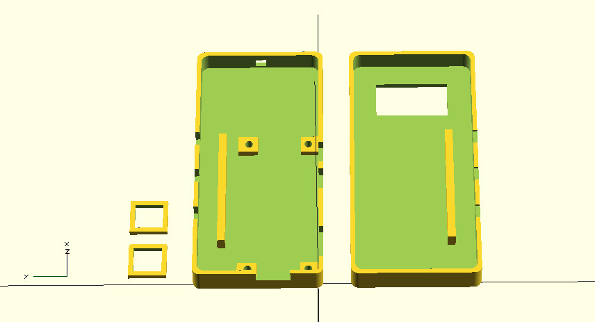
Figure 5 : Case
#!/bin/bash
#init-3.sh

cd /sys/kernel/config/usb_gadget/
mkdir -p g1
cd g1
echo 0x1d6b > idVendor  # Linux Foundation
echo 0x0104 > idProduct # Multifunction Composite Gadget

#echo 0x04b3 > idVendor  # RNDIS id codes
#echo 0x4010 > idProduct #

echo 0x0100 > bcdDevice # v1.0.0
echo 0x0200 > bcdUSB # USB2

mkdir -p strings/0x409
echo "deadbeef01234567890" > strings/0x409/serialnumber
echo "example.com" > strings/0x409/manufacturer
echo "Generic USB Keyboard" > strings/0x409/product

N="usb0"
mkdir -p functions/hid.$N
echo 1 > functions/hid.usb0/protocol
echo 1 > functions/hid.usb0/subclass
echo 8 > functions/hid.usb0/report_length
echo -ne \\x05\\x01\\x09\\x06\\xa1\\x01\\x05\\x07\\x19\\xe0\\x29\\xe7\\x15\\x00\\x25\\x01\\x75\\x01\\x95\\x08\\x81\\x02\\x95\\x01\\x75\\x08\\x81\\x03\\x95\\x05\\x75\\x01\\x05\\x08\\x19\\x01\\x29\\x05\\x91\\x02\\x95\\x01\\x75\\x03\\x91\\x03\\x95\\x06\\x75\\x08\\x15\\x00\\x25\\x65\\x05\\x07\\x19\\x00\\x29\\x65\\x81\\x00\\xc0 > functions/hid.usb0/report_desc

C=1
mkdir -p configs/c.$C/strings/0x409
echo "Config $C: ECM network" > configs/c.$C/strings/0x409/configuration
echo 250 > configs/c.$C/MaxPower
ln -s functions/hid.$N configs/c.$C/

FILE=/home/pi/Disk/usbDisk.img
mkdir -p ${FILE/img/d}
mount -o loop,ro, -t vfat $FILE ${FILE/img/d} # FOR IMAGE CREATED WITH DD
mkdir -p functions/mass_storage.usb0
echo 1 > functions/mass_storage.usb0/stall
echo 0 > functions/mass_storage.usb0/lun.0/cdrom
echo 0 > functions/mass_storage.usb0/lun.0/ro
echo 0 > functions/mass_storage.usb0/lun.0/nofua
echo $FILE > functions/mass_storage.usb0/lun.0/file
ln -s functions/mass_storage.usb0 configs/c.1/

mkdir -p functions/acm.usb0
ln -s functions/acm.usb0 configs/c.1/

mkdir -p functions/ecm.usb0
HOST="48:6f:73:74:50:43" # "HostPC"
SELF="42:61:64:55:53:42" # "BadUSB"
echo $HOST > functions/ecm.usb0/host_addr
echo $SELF > functions/ecm.usb0/dev_addr
ln -s functions/ecm.usb0 configs/c.1/

ls /sys/class/udc > UDC
Figure 6 : USB gadget config script
Finally the boot script starts the user interface controlled by displayButtons.py allowing the user to select items on the small display, controlled using the three push buttons mounted on the side of the box i.e. up, down and select. The three side push buttons control the display cursor, as these are push buttons added a some hardware switch de-bounce, as shown in figure 7, simple CR filter. Resistor vales where just what i had to hand, perhaps would change to 10K and 100.
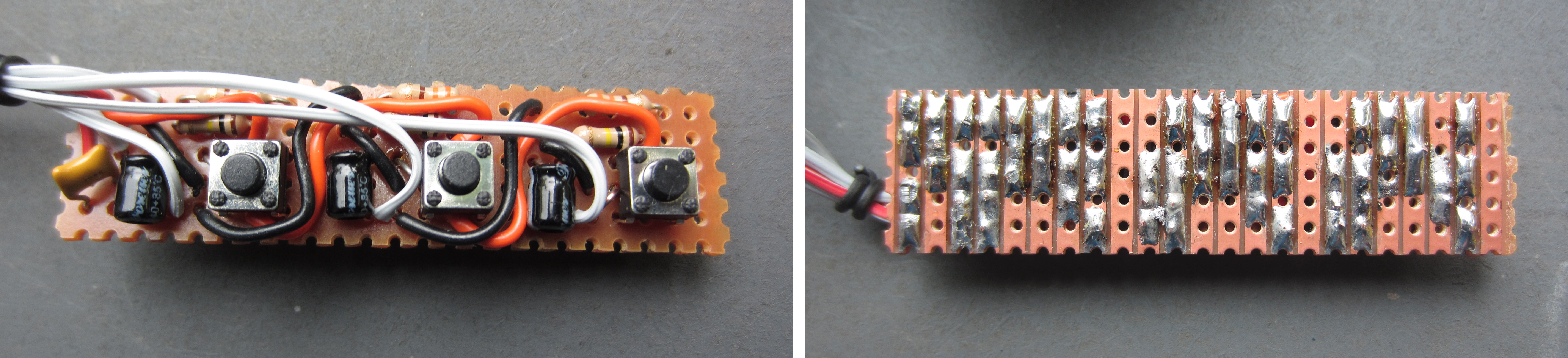
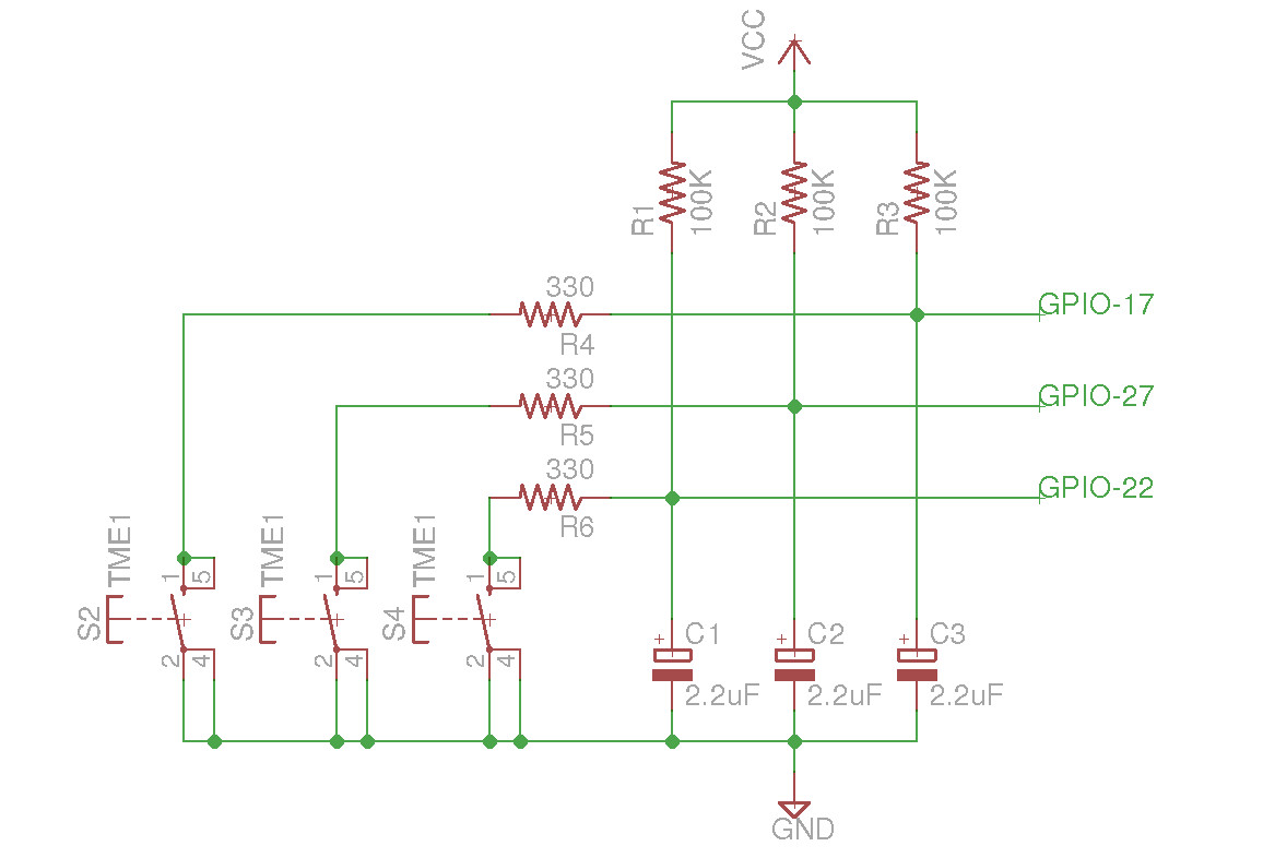
Figure 7 : push_button
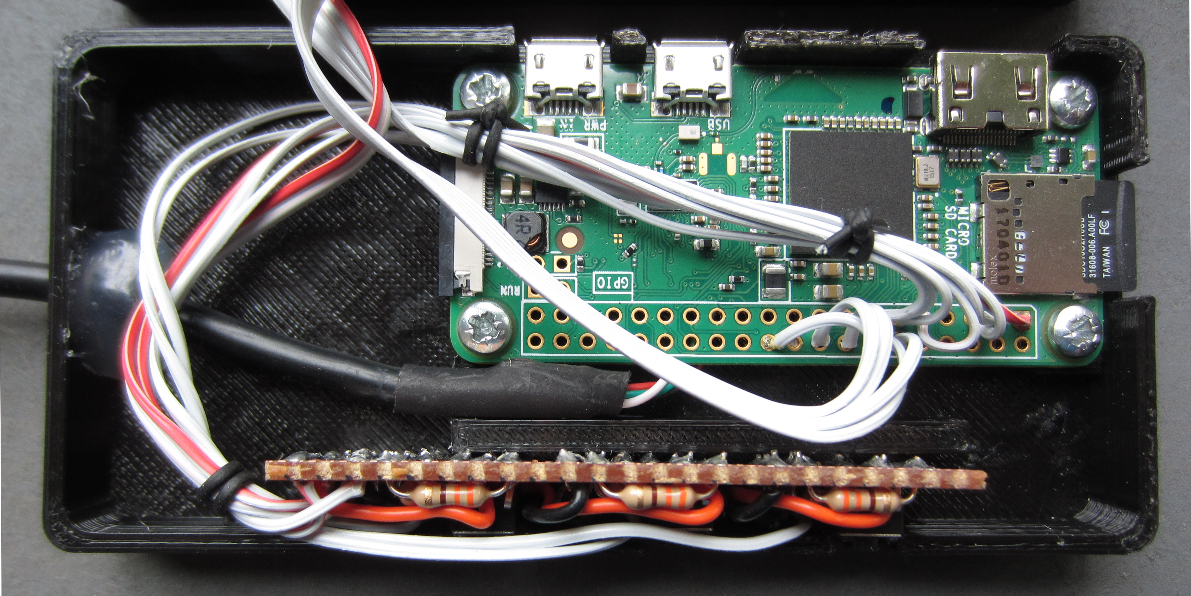
Figure 8 : push_button
The menu screen allows the user to select different functions, at present just got around to doing Ducky scripts and a graceful shutdown, but will add other options later.
#displayButtons.py

import RPi.GPIO as GPIO
import Adafruit_SSD1306
import time

from PIL import Image
from PIL import ImageFont
from PIL import ImageDraw

import subprocess
import os

GPIO.setwarnings(False)
GPIO.setmode(GPIO.BCM)

#Pins 17=bottom, 22=middle, 27=top

GPIO.setup(17, GPIO.IN)
GPIO.setup(27, GPIO.IN)
GPIO.setup(22, GPIO.IN)

def bottom_click(pin):
    global cursorX, cursorY, selection, screen, payloads
    print "bottom button clicked"
    if(screen == 0):
        # DUCKY
        if(selection == 1):
            payloads = os.listdir("/home/pi/Ducky/Payloads")
            screen = 1
            selection = 1
            cursorX = 0
            cursorY = 14
            menu()
        # STATS
        if(selection == 2):
            screen = 2
            cursorX = 0
            cursorY = 14 + cursorS*5
            menu()
        # NU
        if(selection == 3):
            screen = 0
            menu()
        # NU
        if(selection == 4):
            screen = 4
            menu()
        # NU
        if(selection == 5):
            screen = 5
            menu()
        # SHUTDOWN
        if(selection == 6):
            screen = 6
            cursorX = 0
            cursorY = 14 + cursorS*5
            menu()

    # DUCKY
    elif(screen == 1):
        if(selection == 6):
            screen = 0
            selection = 1
            cursorX = 0
            cursorY = 14
            menu()
	else:
            duckyString = "sudo /home/pi/Ducky/go.sh " + payloads[selection-1]
            print duckyString
            os.system(duckyString)

    # STATS
    elif(screen == 2):
        screen = 0
        selection = 1
        cursorX = 0
        cursorY = 14
        menu()

def middle_click(pin):
    global cursorY, cursorS, selection
    print "middle button clicked"
    if(screen == 0 or screen == 1):
        if(selection < 6):
            selection = selection + 1
            cursorY = cursorY + cursorS
            menu()

def top_click(pin):
    global cursorY, cursorS, selection
    print "top button clicked"
    if(screen == 0 or screen == 1):
        if(selection > 1):
            selection = selection - 1
            cursorY = cursorY - cursorS
            menu()

def menu():
    global payloads

    # Draw a black filled box to clear the image.
    draw.rectangle((0,0,width,height), outline=0, fill=0)

    if(screen == 0):
        # MAIN MENU
        size = 9
        offset = 0
        draw.text((left, top),                 "Bad USB Menu",  font=font, fill=255)
        draw.text((left, top+(size*1)+offset), "   Ducky", font=font, fill=255)
        draw.text((left, top+(size*2)+offset), "   Stats",  font=font, fill=255)
        draw.text((left, top+(size*3)+offset), "        ",  font=font, fill=255)
        draw.text((left, top+(size*6)+offset), "   Shutdown",  font=font, fill=255)

        draw.rectangle((cursorX,cursorY,cursorX+cursorW,cursorY+cursorH), outline=255, fill=1)
        draw.line((0,11,74,11), fill=255)

    elif(screen == 1):
        # DUCKY
        size = 9
        offset = 0
        draw.text((left, top),                 "Ducky Scripts",  font=font, fill=255)
        draw.text((left, top+(size*1)+offset), "   " + str(payloads[0]), font=font, fill=255)
        draw.text((left, top+(size*2)+offset), "   " + str(payloads[1]), font=font, fill=255)
        draw.text((left, top+(size*3)+offset), "   " + str(payloads[2]), font=font, fill=255)
        draw.text((left, top+(size*4)+offset), "   " + str(payloads[3]), font=font, fill=255)
        draw.text((left, top+(size*6)+offset), "   Back",  font=font, fill=255)

        draw.rectangle((cursorX,cursorY,cursorX+cursorW,cursorY+cursorH), outline=255, fill=1)
        draw.line((0,11,79,11), fill=255)

    elif(screen == 2):
        # SYSTEM STATS
        stats()

    elif(screen == 3):
        # NU
        print ""

    elif(screen == 4):
        # NU
        print ""

    elif(screen == 5):
        # NU
        print ""

    elif(screen == 6):
        # SHUTDOWN
        size = 9
        offset = 0
        draw.text((left, top), "Shutdown ...",  font=font, fill=255)
        disp.image(image)
        disp.display()
        time.sleep(0.5)
        os.system("shutdown -h now")

    else:
        print "Menu error"

    # Display image.
    disp.image(image)
    disp.display()

def stats():
    # Draw a black filled box to clear the image.
    draw.rectangle((0,0,width,height), outline=0, fill=0)

    cmd = "hostname -I | cut -d\' \' -f1"
    IP = subprocess.check_output(cmd, shell = True )
    cmd = "top -bn1 | grep load | awk '{printf \"CPU Load: %.2f\", $(NF-2)}'"
    CPU = subprocess.check_output(cmd, shell = True )
    cmd = "free -m | awk 'NR==2{printf \"Mem: %s/%sMB %.2f%%\", $3,$2,$3*100/$2 }'"
    MemUsage = subprocess.check_output(cmd, shell = True )
    cmd = "df -h | awk '$NF==\"/\"{printf \"Disk: %d/%dGB %s\", $3,$2,$5}'"
    Disk = subprocess.check_output(cmd, shell = True )

    size = 9
    draw.text((left, top),          "IP: " + str(IP),  font=font, fill=255)
    draw.text((left, top+(size*1)), str(CPU), font=font, fill=255)
    draw.text((left, top+(size*2)), str(MemUsage),  font=font, fill=255)
    draw.text((left, top+(size*3)), str(Disk),  font=font, fill=255)
    draw.text((left, top+(size*6)), "  Back",  font=font, fill=255)

    draw.rectangle((cursorX,cursorY,cursorX+cursorW,cursorY+cursorH), outline=255, fill=1)

    # Display image.
    disp.image(image)
    disp.display()


GPIO.add_event_detect(17, GPIO.FALLING, callback=bottom_click, bouncetime=500)
GPIO.add_event_detect(22, GPIO.FALLING, callback=middle_click, bouncetime=500)
GPIO.add_event_detect(27, GPIO.FALLING, callback=top_click,    bouncetime=500)

RST = None     # on the PiOLED this pin isnt used
disp = Adafruit_SSD1306.SSD1306_128_64(rst=RST, i2c_address=0x3c)
disp.begin()

# Clear display.
disp.clear()
disp.display()

width = disp.width
height = disp.height

cursorX = 0
cursorY = 14
cursorW = 10
cursorH = 5
cursorS = 9

screen = 0
selection = 1
payloads = []

padding = 1
top = padding
bottom = height-padding
left = 1
right = 126

# Create blank image for drawing.
# Make sure to create image with mode '1' for 1-bit color.
image = Image.new('1', (width, height))

# Get drawing object to draw on image.
draw = ImageDraw.Draw(image)

# Load font.
font = ImageFont.load_default()
#font = ImageFont.truetype('Minecraft.ttf', 12)
#font = ImageFont.truetype('visitor1.ttf', 9)
#font = ImageFont.truetype('apple.ttf', 7)

menu()

while True:
    time.sleep(500)
To connect to the Pi remotely you can use either the Serial or Ethernet ports. Being able to SSH into the Pi using a serial link is a must have, very useful, allows you to get the Wifi interface working without having to connect a monitor and a keyboard (as noted, keyboard may no longer work with these mods). Also it more reliable than Ethernet-over-USB when moving between Windows and Linux (also had joys of NetWork managers automatically changing network interface settings). To allow you to log into the Pi over a serial interface at the command line enter raspi-config, then select:
The second option increases the memory available to the processor as we will not be running GPU intensive programs. Using the USB serial port configured in figure 6, you can now log into the Pi using a serial terminal. On the host machine you should see a new terminal device or comm port. Under Linux i see it as /dev/ttyACM0(name may vary), at the command prompt type ls /dev/tty* to identify the new device. Under Windows you can find out the comm port number by running Device Manager and looking under Ports(COM & LPT). To connect to the Pi under Linux, type:
screen /dev/ttyACM0 115200
You may need to press ENTER to display the log-in text, but otherwise good to go. For more info on the screen command see LINK, the key command to remember is CTL+A k, if you wish to stop screen running. Under Linux the ECM Ethernet-over-USB module works out of the box, just need to decide on the MAC addresses i.e. for HOST and Pi network interfaces, i went with the tutorial values. If you run ifconfig on the PC the network USB device appears for me as eth2, to assign an IP address enter:
sudo ifconfig eth2 192.168.0.1
Using the serial terminal do the same on the Pi, if you run ifconfig on the network USB device appears for me as usb0, i assigned it the IP address 192.168.0.2. To connect to the Pi simply type on the PC command line (and enter password when prompted):
ssh pi@192.168.0.2
Problem number 1, the Linux network manager resets the IP address. To stop this had to kill the default network manager on the PC. Also have troubles when you are working under Windows as by default it does not recognise ECM devices LINK:
"The main industry protocols are (in chronological order): Remote NDIS (RNDIS, a Microsoft vendor protocol), Ethernet Control Model (ECM), Ethernet Emulation Model (EEM), and Network Control Model (NCM). The latter three are part of the larger Communications Device Class (CDC) group of protocols of the USB Implementers Forum (USB-IF)."
To fix this issue found these solutions, but have not had a chance to try them out yet
This one worked as tutorial, but a slightly quicker method of creating a 2GB disk image:
fallocate -l 2048M usbDisk.img
mkfs.fat usbDisk.img
Renamed disk to "DUCKY" using the standard Windows file manager. Stored on this disk are some useful tools : LINK.
The configuration script shown in figure 6 create a Human Interface Device (hid) keyboard (/dev/hidg0). To send characters across the USB cable to the PC 'all' you need to do is sent the correct control sequences to this device. To do this i found a nice piece of C code: LINK, compile this up to produce the executable hid-gadget-test, you can then just pass/pipe characters to this program, sending them to the PC:
sudo chmod -R 777 /dev/hidg0
echo 'a' | hid-gadget-test /dev/hidg0 keyboard
Using this we can now create and use Ducky scripts LINK. To convert Ducky Scripts into a suitable format/sequence of characters for hid-gadget-test i modified this python code LINK. My coding i would describe as functional :), the important thing is it works.
Update: 5 Sep 2017, this project paused, last used as in an open day demo to illustrate the dangers of plugging a USB device of unknown origins into your computer :). Thing i would like to play with are:

This work is licensed under a Creative Commons Attribution-NonCommercial-NoDerivatives 4.0 International License.
Contact details: email - mike.freeman@york.ac.uk, telephone - 01904 32(5473)
Back